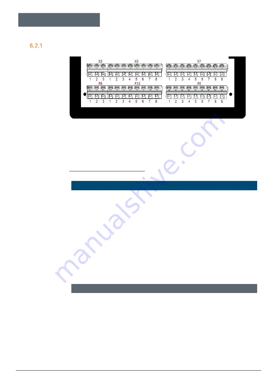
Electrical connections
Ex p control unit
Motor Purge Controller
Page 36 of 96
01-37A2-7D0003_Operating instructions_MPC_20210923_0_en.docx
Rev. 0
Terminals “Ex e”
6.2.1.1
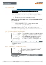
Terminal row “X3”
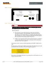
There are two different connection designs for the control units of the MPC
series. When connecting the power supply, please note the type and design.
APEXmpc / SILASmpc, standard
ATTENTION
PROPERTY DAMAGE CAUSED BY INCORRECT SUPPLY VOLTAGE.
The internal electronics of the control unit could be destroyed.
Before activating the supply voltage, compare the value of the supply
voltage with the value printed on the controller.
Active protective measure.
As an active protective measure, the supply voltage must be
protected by a fuse (min. 1500 A breaking capacity) and an FI circuit
breaker.
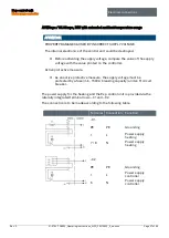
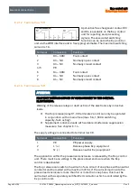
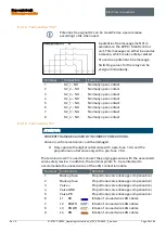
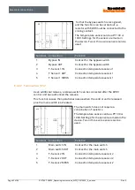
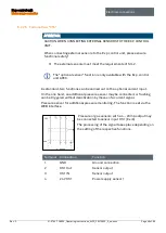
The supply voltage is connected to terminal row X3.
Terminal
Connection
Function
1
PE
PE power supply
2
L (+)
Phase (+ conductor) power supply
3
N (-)
Neutral (GND) power supply


