Ex p control unit
Motor purge controller
Electrical connections
Rev. 0
01-37A2-7D0003_Operating instructions_MPC_20210923_0_en.docx
Page 39 of 96
6.2.1.4
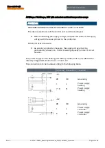
Terminal row “X12”
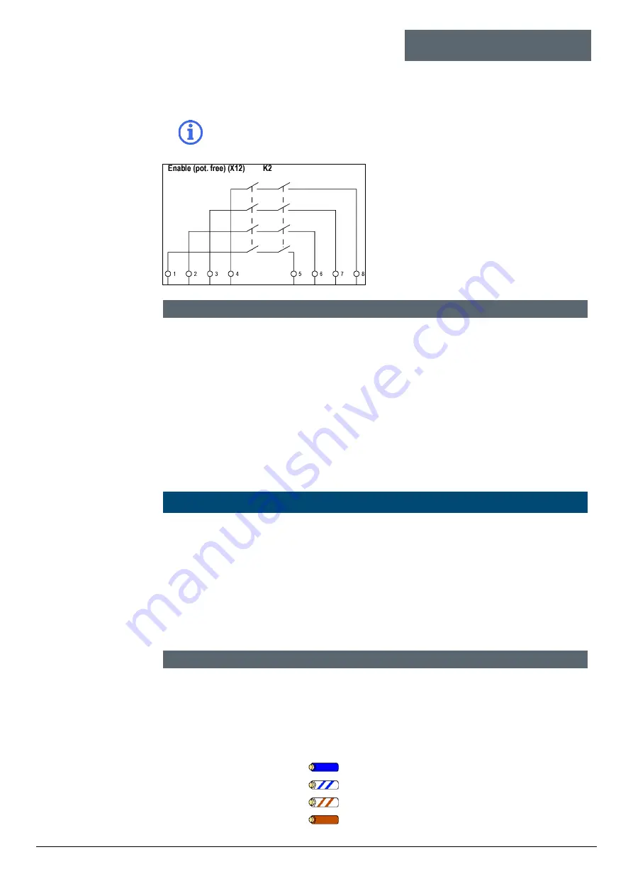
Potential-free signal K2 can be classified as a pure release
according to SIL when used.
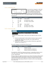
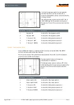
A potential-free message (4x NO) is
available on the APEX / SILAS control
unit. This message can either be used as
a release, which is also safety-related.
Or used as a potential-free message.
Switching values for the relay can be
assigned individually.
Terminal
Connection
Function
1
K2_1 - NO
Normally open contact
2
K2_2 – NO
Normally open contact
3
K2_3 – NO
Normally open contact
4
K2_4 – NO
Normally open contact
5
K2_1´ - NO
Normally open contact
6
K2_2´ - NO
Normally open contact
7
K2_3´ - NO
Normally open contact
8
K2_4´ - NO
Normally open contact
6.2.1.5
Terminal row “X7”
ATTENTION
PROPERTY DAMAGE CAUSED BY INCORRECT PRECAUTIONS.
Valve or control electronics could be damaged.
Only operate the digital outlet valve with a pre-fuse 1.0 A and the
proportional outlet valve only with a pre-fuse 1.6 A.
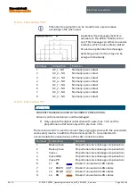
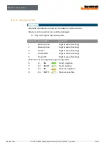
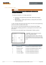
The terminal row X7 is used to connect the purging gas valve with the associated
valve safety device. In addition, the terminal points 6 - 9 are intended to
accommodate the unused wires of the LAN connection cable.
Terminal
Connection
Function
1
Backup fuse
Proportional valve (leakage compensation)
2
Backup fuse
Proportional valve (leakage compensation)
3
Valve +
Proportional valve (leakage compensation)
4
Valve GND
Proportional valve (leakage compensation)
5
Valve PE
Proportional valve (leakage compensation)
6
L1
BU
Intake of unused wire LAN cables
7
L2
BUWH
Intake of unused wire LAN cables
8
L3
BNWH
Intake of unused wire LAN cables
9
L4
BN
Intake of unused wire LAN cables


