background image

EU Declaration of Conformity 

Ex p control unit 

Motor Purge Controller 


Page 94 of 96 

01-37A2-7D0003_Operating instructions_MPC_20210923_0_en.docx 

Rev. 0 

14.2


EU Declaration of Conformity SILAS

mpc


Summary of Contents for APEXmpc

Page 1: ...Manual Ex p Control Unit APEXmpc SILASmpc...

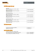
Page 2: ...0 Fax 49 7931 597 480 Support info bartec de Internet www bartec de Operating instructions Safety manual Ex p control units APEXmpc type 07 37A2 2211 M5 ATEX IECEx zone 1 21 SILASmpc type A7 37S2 211...

Page 3: ...Page 2 of 96 01 37A2 7D0003_Operating instructions_MPC_20210923_0_en docx Rev 0...

Page 4: ...voidance of property damage 13 Short circuit due to improper connection 13 Triggering of the safety function 13 EMV compliant connection 13 Storage at too high a temperature 13 Aggressive cleaning age...

Page 5: ...anual leakage air boost 24 p operator panel 24 Ex i separation box 24 Programming approval 24 Programming cable 24 4 Transport and storage 25 4 1 Scope of delivery 25 4 2 Packaging 25 4 3 Transport 25...

Page 6: ...Query system status 53 7 12 Read out data containers 54 7 13 Purge parameters 55 Purge mode tab 55 Pressure parameter 58 Characteristic curve 59 Enclosure related parameters tab 59 7 14 Manual purgin...

Page 7: ...control unit APEXmpc 83 11 2 Ex p control unit SILASmpc 84 11 3 Pressure monitor mpv 85 Pressure monitor mpv standard 85 Pressure monitor mpv extended temperature range 85 11 4 Recommended purge gas q...

Page 8: ...lation and start up Only qualified personnel have the necessary specialist knowledge to correctly interpret the general safety notes and warnings in these operating instructions as well as to put them...

Page 9: ...nent damage WARNING WARNING indicates a hazardous situation which if the safety measures are not observed can lead to serious injuries without permanent damage CAUTION CAUTION indicates a hazardous si...

Page 10: ...nce with IEC 61508 Table 1 Symbols and means of illustration 1 2 Technical changes The current versions of the data sheets operating instructions certificates and EU declarations of conformity as well...

Page 11: ...category 3GD and temperature class T4 or for use in dust with surface temperatures of T130 C The permissible operating data of the device used must be observed Improper use Any other use is improper a...

Page 12: ...ded if these can be linked to one or more of the following causes Improper use of the control unit Improper assembly commissioning operation and maintenance of the control unit Failure to observe the...

Page 13: ...fects of moisture Operational safety information Installation Before the installation it must be checked that all components and documents are available Inspection According to EN IEC 60079 17 IEC 600...

Page 14: ...is the device ready for operation again In Ex applications only one device and one electronics module with the appropriate Ex approval may be used Order the spare parts from your distributor The seri...

Page 15: ...found in the respective state law The symbol on the product the operating instructions and or the packaging refers to these provisions By separating the material as well as recycling and disposing of...

Page 16: ...x BVS 19 0038 X EAC Eurasian Economic Union Marking 1Ex e mb ib ib px ia Ga IIC T5 Gb X 1Ex e mb ib ib px ia Ga IIC T4 Gb X Ex tb ib px ia Da IIIC T95 C Db X Ex tb ib px ia Da IIIC T130 C Db X Test ce...

Page 17: ...3 0 Safety regulations for electrical measuring control regulating and laboratory devices Part 1 General requirements EN 61000 6 4 2007 A1 2011 IEC 61000 6 4 2018 Edition 3 0 Electromagnetic compatibi...

Page 18: ...4 IEC 60079 31 2013 Edition 2 0 IEC 60079 31 2013 Hazardous areas Part 31 Device dust explosion protection through housing t EN 61010 1 2010 IEC 61010 1 2010 Edition 3 0 Safety regulations for electri...

Page 19: ...e operating environment Repeat checks The SIL qualification of components is documented within this manual This chapter summarises all safety relevant characteristics that users and planners need for...

Page 20: ...erval 1 year Category 3 Response time The reaction time of the Ex p control unit APEX to safety relevant functions without specific user delay times is less than 2 seconds With the Ex p control unit A...

Page 21: ...ow rate determined during the initial start up Since a safe state in the housing is only achieved at the beginning of the operating phase the Ex p control unit and its system components must be design...

Page 22: ...Xmpc or SILASmpc control unit is shown below The protective housing is designed according to Ex e and can be mounted outside onto the pressurised enclosure motor Pos Description Protective housing Ex...

Page 23: ...ailable in the extended temperature range version This is approved for a range from 50 C to 50 C instead of 25 C to 50 C The extended temperature range is implemented through internal heating which is...

Page 24: ...c connections Mounting flange MPV pressure monitor with an extended temperature range Each APEX complete control unit in the MPC design has a separate MPV pressure monitor attached to the motor The fo...

Page 25: ...can be connected or disconnected during operation and it is therefore not necessary for it to be constantly connected to the control unit The utilisation for the p operator panel is described in a sep...

Page 26: ...ontrol unit is delivered packed in foil on a pallet and or in cardboard boxes Please dispose of the packaging materials at designated disposal points Observe the applicable national regulations for di...

Page 27: ...ontal position and at a temperature between 20 C and 60 C in the original packaging The environment must be dry dust free and low vibration Store the control unit for a maximum of 2 years For warehous...

Page 28: ...er specific structures Please observe the chapters on installation and electrical connections 5 1 General Mount the APEXmpc or SILASmpc and system accessories in the desired position using the fasteni...

Page 29: ...ntroller is designed with a G 1 internal thread connection Purge gas supply to the motor The purge gas supply from the motor purge controller to the protected motor is designed with a G 1 external thr...

Page 30: ...Ex p control unit Motor purge controller Installation Rev 0 01 37A2 7D0003_Operating instructions_MPC_20210923_0_en docx Page 29 of 96 5 3 Flow chart...

Page 31: ...nsion earth and short circuit cover or cordon off neighbouring live parts The connection terminals with type of protection Ex e or Ex i are located on the connection board of the Ex p control unit Ter...

Page 32: ...space between the shield bus and the connection terminal Check that no cables are loose or protrude AVOID DAMAGE TO THE SEAL Cancellation of the Ex protection concept Visual inspection of the seal whe...

Page 33: ...n of the Ex p control unit under the influence of EMC 6 1 2 1 Lines and connections Please note the following points Divide the lines into groups Power cables power lines power supplies Signal lines s...

Page 34: ...flow through the entire cable cross section but predominantly on the outer skin of a conductor Please note the following points Always connect the shield over a large area using metal cable clamps Avo...

Page 35: ...ure failure due to the overvoltage that occurs when the current flow through an inductive load is interrupted In addition protective circuits limit the electrical interference that occurs when switchi...

Page 36: ...Ex p control unit Motor purge controller Electrical connections Rev 0 01 37A2 7D0003_Operating instructions_MPC_20210923_0_en docx Page 35 of 96 6 2 Electrical wiring APEXmpc SILASmpc...

Page 37: ...NTION PROPERTY DAMAGE CAUSED BY INCORRECT SUPPLY VOLTAGE The internal electronics of the control unit could be destroyed Before activating the supply voltage compare the value of the supply voltage wi...

Page 38: ...of the supply voltage with the value printed on the controller Active protective measure As an active protective measure the supply voltage must be protected by a fuse min 1500 A breaking capacity an...

Page 39: ...ys or destruction of the electronics by inductive loads The Ex p release relay K1 X8 terminals 2 and 3 can only be operated in conjunction with a mains fuse max 5 A 1 500 A switching capacity fast act...

Page 40: ...tact 8 K2_4 NO Normally open contact 6 2 1 5 Terminal row X7 ATTENTION PROPERTY DAMAGE CAUSED BY INCORRECT PRECAUTIONS Valve or control electronics could be damaged Only operate the digital outlet val...

Page 41: ...Valve or control electronics could be damaged Only use original mpc spare parts Terminal Connection Function 1 Backup fuse Digital valve flushing 2 Backup fuse Digital valve flushing 3 Valve Digital...

Page 42: ...d that there is no explosive atmosphere for the period of start up or where necessary protective measures against the risk of explosion have been taken fire permit A label on the bypass key switch sta...

Page 43: ...Connection temperature sensor 1 5 T Sensor 1 MESS Connection temperature sensor 1 6 2 2 2 Terminal row X14 As an additional release a release switch can be connected after the APEX control unit has a...

Page 44: ...se must be connected and activated This is only to be connected while parameters are being actively changed After changing or adapting parameters a subsequent functional test must be carried out This...

Page 45: ...p control unit APEXmpc As standard two functions can be carried out on the optional current input On the one hand an additional pressure sensor may be connected or flushing can be triggered without de...

Page 46: ...Ex p control unit APEX As standard two functions can be carried out on the optional current input On the one hand an additional pressure sensor may be connected or flushing can be triggered without de...

Page 47: ...onductor Function 1 3V3V_HMI BK Power supply 2 GND WH Ground connection 3 HMI_RX RD Data line 4 HMI_TX YE Data line 6 2 2 7 Terminal row measuring board The pressure sensor board belonging to the Ex p...

Page 48: ...ontrol unit is supplied with a fixed IP address as standard Standard IP address delivery status 192 168 11 101 The following options are available for establishing a connection between laptop and PC L...

Page 49: ...Protocol Version 4 TCP IPv4 Change Obtain IP address automatically to Use the following IP address by clicking on it Enter IP address 192 168 11 99 at IP address Enter subnet mask 255 255 0 0 Confirm...

Page 50: ...er changing the language query of status and messages is possible Level 2 User access User ID user Password 0000 Note Changing the settings is possible in connection with a set programming switch 7 4...

Page 51: ...nter the value 250 Confirm with the Enter key The following window opens This is to confirm and check the changed parameter value 7 6 LED displays LED Colour Function p1 Green Minimum pressure Lights...

Page 52: ...re WEB interface Ex p Parameter Info Save Settings Purge parameter Purge mode Print parameter Characteristic curve Housing parameter Home page Status Messages Parameter Fault memory Temperature sensor...

Page 53: ...ghtness of the LCD display on the p Operator panel can be set in the Display tab 7 9 Password menu A new password can be stored for the guest and user in the Password tab 7 10 Network menu All network...

Page 54: ...st Password guest Confirm with Enter The start screen opens Status Displays the target values and measured actual values In addition a pressure time diagram is displayed Messages Displays plain text m...

Page 55: ...192 169 1 101 info_operator json The username password must be entered User name operator Password operator Response from the control unit szFileName info_operator json _0x0401 49 _0x0101 1 _0x0402 65...

Page 56: ...atic Automatic determination of purging time based on the pressure value p5 At the beginning of the purging phase the control unit regulates to 87 5 of the permissible pressure value p5 maximum purgin...

Page 57: ...guration The following purging programmes with functions are available for purging a pressurised motor with the Motor Purge Controller Purging programmes for gas application Programme Application Func...

Page 58: ...t purging time and confirm with Enter e g 10 minutes 30 seconds Confirm pop up window with the changed value Deactivate programming switch Call up the Status menu 7 13 1 5 Flushing DANGER DEATH OR SER...

Page 59: ...p2 is a pre alarm of the internal pressure of the enclosure This value is monitored by the Ex p control unit If the pressure falls below this value it is possible to set off an alarm via a signal rel...

Page 60: ...reading the type designation on the pressure monitor and selecting the associated characteristic curve Orifice Diameter mm MPV 8 50 Type 17 51P3 3803 mpv 2 9 100 Type 17 51P3 3903 mpv 3 Enclosure rela...

Page 61: ...parameters menu Use the keypad to increase the setpoint p3 and confirm with the Enter key e g 15 mbar Confirm pop up window with the changed value Deactivate programming switch Call up the Status men...

Page 62: ...asuring range of the sensor must be entered Confirm pop up window with the changed value s Call up the Pressure parameters menu and enter the required setpoints for the optional pressure sensors pa an...

Page 63: ...age s in the Relay K2 column by clicking on the corresponding button Click on the K1 button The button changes from to Confirm pop up window with the changed value s Activate the specific message s in...

Page 64: ...it is set on C Setting the temperature switching values The temperature switching values for temperature sensors 1 to 3 are configured in the Temperature sensors menu Procedure Call up the menu page T...

Page 65: ...de parameter switch activated and password entered the pressure values are displayed in Pa Settings are made in the Pa General The following procedure for setting the function parameters is recommende...

Page 66: ...supply is connected Log into the user level of the WEB interface in order to carry out the configuration The structure of the chapters corresponds to the flow chart in Chapter 7 1 and can thus be work...

Page 67: ...all purging programs is po p1 so that the other phases can be initiated Procedure Connect the PC with the Ex p control unit and activate the programming switch Log into the WEB interface with the use...

Page 68: ...Pa 20 mbar A pop up window displaying the changed value opens Confirm Deactivate programming switch The Ex p control unit changes from programming mode to control monitoring mode Press the F5 key on...

Page 69: ...tch Log into the WEB interface with the user level Call up the menu Purging parameters Pressure parameters Enter the parameter po operating overpressure and confirm e g 250 Pa 2 5 mbar The value po is...

Page 70: ...o p1 so that the other phases can be initiated Procedure Connect the PC with the Ex p control unit and activate the programming switch Log into the WEB interface with the user level Call up the menu P...

Page 71: ...p1 1 0 mbar 100 Pa p2 1 5 mbar 150 Pa p3 automatic determination by Ex p control unit p4 P5 Application dependent e g pressure sensitive components Procedure Connect the PC with the Ex p control unit...

Page 72: ...aracteristic curve tab This must be set correctly for the calculation of the automatic purging time The pressure monitor used can be selected by clicking on the button Selection table Parameter Measur...

Page 73: ...e any explosive gas air mixture or to dilute it to a non hazardous concentration before the possible ignition sources in the pressurised enclosure are switched on This process prepares the pressurised...

Page 74: ...llations in the pressurised enclosure are switched on via a relay integrated in the control electronics If the enclosure pressure falls below the set minimum values during the operating phase all elec...

Page 75: ...to three phases The three phases are divided into the preparation pre purge and operating phases 9 3 Querying system status Logging into the web interface by opening the browser and entering the IP ad...

Page 76: ...ed actual values In addition a pressure time diagram is output Messages Displays plain text messages about the system status Status display Upper area Listing of setpoint values with comparison of act...

Page 77: ...ork Maintenance intervals MAINTENANCE INTERVALS If the unit is operated properly and the installation instructions and ambient conditions are observed maintenance is recommended in accordance with the...

Page 78: ...ome into contact with seals Regular maintenance Depending on the purity of the purge air used the inlet and outlet of the control unit must be inspected regularly for any contamination e g oil dust et...

Page 79: ...The protected devices are switched on without pre purge Bypass activated Deactivate bypass Wrong purging program activated Check purging program During the pre purging the purging gas valve switches...

Page 80: ...age The control unit does not switch on the electrical devices after the pre purging phase The pressure in the enclosure is higher than the switching value p4 Reduce the flow rate of the leakage air n...

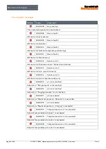
Page 81: ...Alarm messages are messages which lead to the shutdown of the protected equipment 10 4 2 1 Positive messages Status Code Plain text 00000001 Purging process The control unit has started the purging pr...

Page 82: ...switch or jumper HS_IN HS_OUT is not closed 00000007 p2 is not reached Setpoint p2 Pre alarm is not reached 00000008 p4 exceeded Setpoint p4 Maximum pressure operation is exceeded 00000009 p5 exceede...

Page 83: ...or Pressure sensor Sensor board status 00000013 Sensor error 2 HW test error opt current sensors 00000014 Sensor error 3 HW test error ext temperature sensors 00000015 p1 is not reached Setpoint p1 Mi...

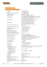
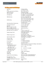
Page 84: ...Voltage DC Variant 24 V dc to 44 V dc Mains Voltage AC Variant 100 V ac to 230 V ac Current consumption control unit 2 A Maximum power consumption 25 W incl purge valve Release relay K1 SIL 2 potenti...

Page 85: ...ac to 230 V ac Current consumption control unit 2 A Maximum power consumption 25 W incl purge valve Release relay K1 SIL 2 potential related NO contacts 230 V ac 5 A AC1 or 24 V dc 5 A DC1 Release rel...

Page 86: ...lange 165 mm 220 mm Signal lines 2x pipe connection 10mm Installation location independent Pressure monitor mpv extended temperature range Parameter Technical details Product mpv2 mpv3 Type 17 51P3 38...

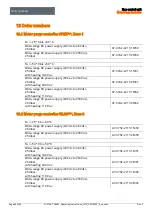
Page 87: ...ge DC power supply 20 Vdc to 48 Vdc 25 mbar with heating 110 V ac 07 37A2 2211 1M52 Wide range AC power supply 90 Vac to 253 Vac 25 mbar with heating 110 V ac 07 37A2 2211 2M52 12 2 Motor purge contro...

Page 88: ...60 C stainless steel V4A 17 51P3 3803 0401 MPV3 orifice 100 mm Ta 50 C to 60 C stainless steel V4A 17 51P3 3903 0401 with heating AC 110 V MPV2 orifice 50 mm Ta 50 C to 60 C stainless steel V4A 17 51...

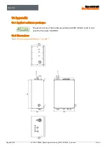
Page 89: ...88 of 96 01 37A2 7D0003_Operating instructions_MPC_20210923_0_en docx Rev 0 13 Appendix 13 1 Applied software packages The service area of the hardware software APEX SILAS control unit uses the freewa...

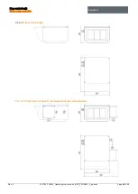
Page 90: ...p control unit Motor purge controller Appendix Rev 0 01 37A2 7D0003_Operating instructions_MPC_20210923_0_en docx Page 89 of 96 Dimensions mpv 13 2 2 1 Dimensions mpv with extended ambient temperatur...

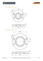
Page 91: ...Appendix Ex p control unit Motor Purge Controller Page 90 of 96 01 37A2 7D0003_Operating instructions_MPC_20210923_0_en docx Rev 0 13 2 2 2 Flange dimensions mpv2 13 2 2 3 Flange dimensions mpv3...

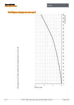
Page 92: ...Motor purge controller Appendix Rev 0 01 37A2 7D0003_Operating instructions_MPC_20210923_0_en docx Page 91 of 96 13 3 Diagram of purge air curve mpv 2 The purge air curve does not take any leakage lo...

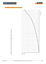
Page 93: ...trol unit Motor Purge Controller Page 92 of 96 01 37A2 7D0003_Operating instructions_MPC_20210923_0_en docx Rev 0 13 4 Diagram of purge air curve mpv 3 The purge air curve does not take any leakage lo...

Page 94: ...unit Motor purge controller EU Declaration of Conformity Rev 0 01 37A2 7D0003_Operating instructions_MPC_20210923_0_en docx Page 93 of 96 14 EU Declaration of Conformity 14 1 EU Declaration of Confor...

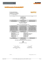
Page 95: ...EU Declaration of Conformity Ex p control unit Motor Purge Controller Page 94 of 96 01 37A2 7D0003_Operating instructions_MPC_20210923_0_en docx Rev 0 14 2 EU Declaration of Conformity SILASmpc...

Page 96: ...Ex p control unit Motor purge controller Notes Rev 0 01 37A2 7D0003_Operating instructions_MPC_20210923_0_en docx Page 95 of 96 15 Notes...

Page 97: ...Notes Ex p control unit Motor Purge Controller Page 96 of 96 01 37A2 7D0003_Operating instructions_MPC_20210923_0_en docx Rev 0...

Page 98: ...bartec com BARTEC BARTEC GmbH Max Eyth Str 16 97980 Bad Mergentheim Germany Tel 49 7931 597 0 Mail info bartec com 01 37A2 7D0003 ESS 413876...

Reviews: