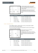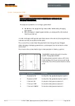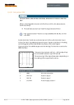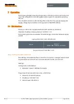
Ex p control unit
Motor purge controller
Electrical connections
Rev. 0
01-37A2-7D0003_Operating instructions_MPC_20210923_0_en.docx
Page 33 of 96
6.1.2.2
Grounding lines
The grounding of a system fulfils protective and functional measures.
Please note the following points:
Grounding lines should be as short as possible.
Avoid ground loops.
Use ground straps with a width of at least 10 mm.
6.1.2.3
Shielding
In order to ensure the fail-safe operation of a system, cables with the largest
possible surface (not cross-section) are important. High-frequency currents do
not flow through the entire cable cross-section, but predominantly on the outer
skin of a conductor.
Please note the following points:
Always connect the shield over a large area using metal cable clamps.
Avoid connecting the shield with long additional wires.
Backup fuse
ATTENTION
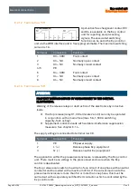
NOTE THE NOMINAL CURRENT OF THE ENABLING CIRCUIT (K1) AND ADD
THIS TO THE FOLLOWING DATA. THE FOLLOWING VALUES ARE FOR THE EX P
CONTROL UNIT ONLY.
If the dimensions are too small, the Ex p control unit could be destroyed.
Nominal current (controller) + nominal current enabling circuit (K1).
Variant
APEX, DC
APEX, AC
Nominal current control unit
>= 3,15 A
>= 2 A
Nominal voltage control unit
>= 63 V DC
>= 277 V AC
Response time
delayed
delayed
Breaking current
>= 1,5 kA
>= 1,5 kA
Melting integral
12… 34 A²s
9,7… 14,7 A²s

