


Инструкция по эксплуатации
Instructions for use
IU 14-223
редакция
4
от
30.05.2017
страница
8
из
18
Настоящий документ является собственностью BARTEC FEAM. Охраняется авторским правом. Частичное или полное воспроизведение разрешено только с разрешения BARTEC FEAM.
The present document is property of BARTEC FEAM. Its copyright in any format, whole or partial, must be before authorized by BARTEC FEAM.
IU 14-223_r4_rus
проводников под напряжением электрических цепей НЕ Ex-i (со степенью
изоляции
1500 В) и цепей Ex-i (со степенью изоляции
500 В).
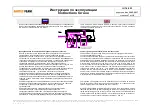
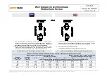
Должно обеспечиваться минимальное расстояние 50 мм во всех направлениях
между соединительными элементами электрических цепей Ex-i и между цепями
НЕ Ex-i или стенками корпуса (см. РИС. 1).
There must be a minimum distance of 50 mm, measured in every direction, between
the connection component of Ex-i circuits and those NOT Ex-i circuits or between the
walls of the enclosures (see FIG.1).
-
Блок питания
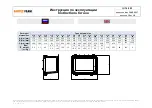
Данное устройство служит для размещения электрического и электронного
оборудования, предназначенного для систем управления питания.
Ввод в эксплуатацию электрического и электронного оборудования должен
производиться исключительно в соответствии с указаниями, содержащимися в
технических паспортах или каталоге поставщика, с соблюдением применимых
стандартов, относящихся к изготовлению электрических щитов низкого
напряжения EN 60439, и общепринятых норм; оборудование должно находиться
на расстоянии не менее 15 мм от внутренних стенок корпусов и не должно
образовывать узких пустых каналов во избежание явлений предварительного
напряжения в случае внутреннего взрыва. Дополнительное оборудование,
установленное на крышке (кнопки, рычаги управления, сигнальные
индикаторы...) установлены в количестве и способом, предусмотренными в
документации, прилагаемой к типовому сертификату оценки СЕ. Для
обеспечения в любой момент полного соблюдения класса температуры корпуса
выделение тепла устройствами, содержащимися внутри корпусов, должны быть
таким, чтобы соблюдались ограничения, указанные в сертификате.
Клеммы оборудования и составные клеммы должны использоваться для ввода
и подключения проводников допустимого типа и сечения, при этом значения
напряжения и тока не должны превышать параметры, указанные
производителем.
- Power unit
This apparatus is made for the housing of electrical and electronic equipment intended
for power systems.
The electrical and electronic equipment must be installed according to the instructions
on the supplier’s instruction sheet or catalogue, in accordance with the requirements
established from the certificate standards to apply for the realisation of the electrical
panel with low voltage IEC 61439 and from the art status; the equipments themselves
must maintain the distances of the least 15 mm from the internal walls of the
enclosures and must not create limited tubes of space to avoid eventual phenomenon
of pre stress in case of internal explosion . The accessories mounted on the cover
(push-
buttons, handles, pilot lamps…) are installed in the quantities and conditions
provided from the documents enclosed to the EC-type examination certificate. To
assure in every moment the complete respect of the temperature class assigned to
the enclosure, the thermal dissipation of the devices contained inside of the enclosures
must respect the limits indicated in the certificate.
The terminals of the equipment and the modular ones must be used with the insert
and the connection of the wires of type and section allowed, for voltage and current
values not higher than ones indicated from the constructor.
3.3
Отверстия для ввода кабеля и монтаж дополнительного
оборудования
3.3
Cable entry holes and mounting of accessories
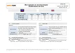
На корпусах могут предусматриваться или выполняться резьбовые отверстия на
стенках, крышке и, в некоторых случаях, на дне для прикручивания дополнительного
оборудования управления или сигнализации, или для ввода кабелей.
ПРИМЕЧАНИЕ. Все механические операции могут выполняться
исключительно производителем, если от него не получено специальное
разрешение.
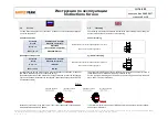
Количество и размер отверстий должны соответствовать указаниям,
предоставленным производителем, в соответствии с типовыми испытаниями,
проведенными для сертификации корпусов. Рядом с каждым резьбовым
отверстием размещена пластина с идентификацией типа и диаметра резьбы.
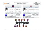
Дополнительное оборудование, используемое для кабельных вводов, должно
быть сертифицировано в соответствии с директивой согласно стандартам
ГOCT P 51330.0-99 и ГOCT P 61241-0-2007.
The enclosures may have, or be given, threaded holes on the walls and on the cover,
allowing to screw the control or signalling accessories, or for the cable entry.
NB. All mechanical manufacturing may only be executed by manufacturer, unless
of express authorization of itself.
The quantity and size of the holes must comply with the indications supplied by the
manufacturer, in accordance with the type of tests carried out for the certification of
enclosures. In proximity of any threaded hole, is placed a tag with identification of type
and diameter of thread.
The accessories used for cable entry must be certified in accordance with IEC
Certification Scheme and to comply with Standards IEC60079-0 and IEC60079-1.


