Ex p Control Unit
SIEMENS Set
Installation
Rev. 0
01-37A2-7D0004_SIEMENS_Manual_Exp-Control-Unit_20220216_0_en.docx
Page 25 of 80
Disclaimer: We reserve the right to make technical changes. Changes, errors and printing errors do not justify claims for damages.
5
Installation
Before starting work, find out about the general safety
instructions (see Chapter 2 Safety instructions).
Deviations in assembly may arise in the case of customized set-
ups.
Carry out the installation according to the following sections, unless otherwise
agreed for customer-specific control units.
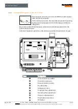
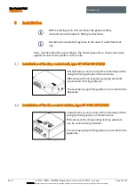
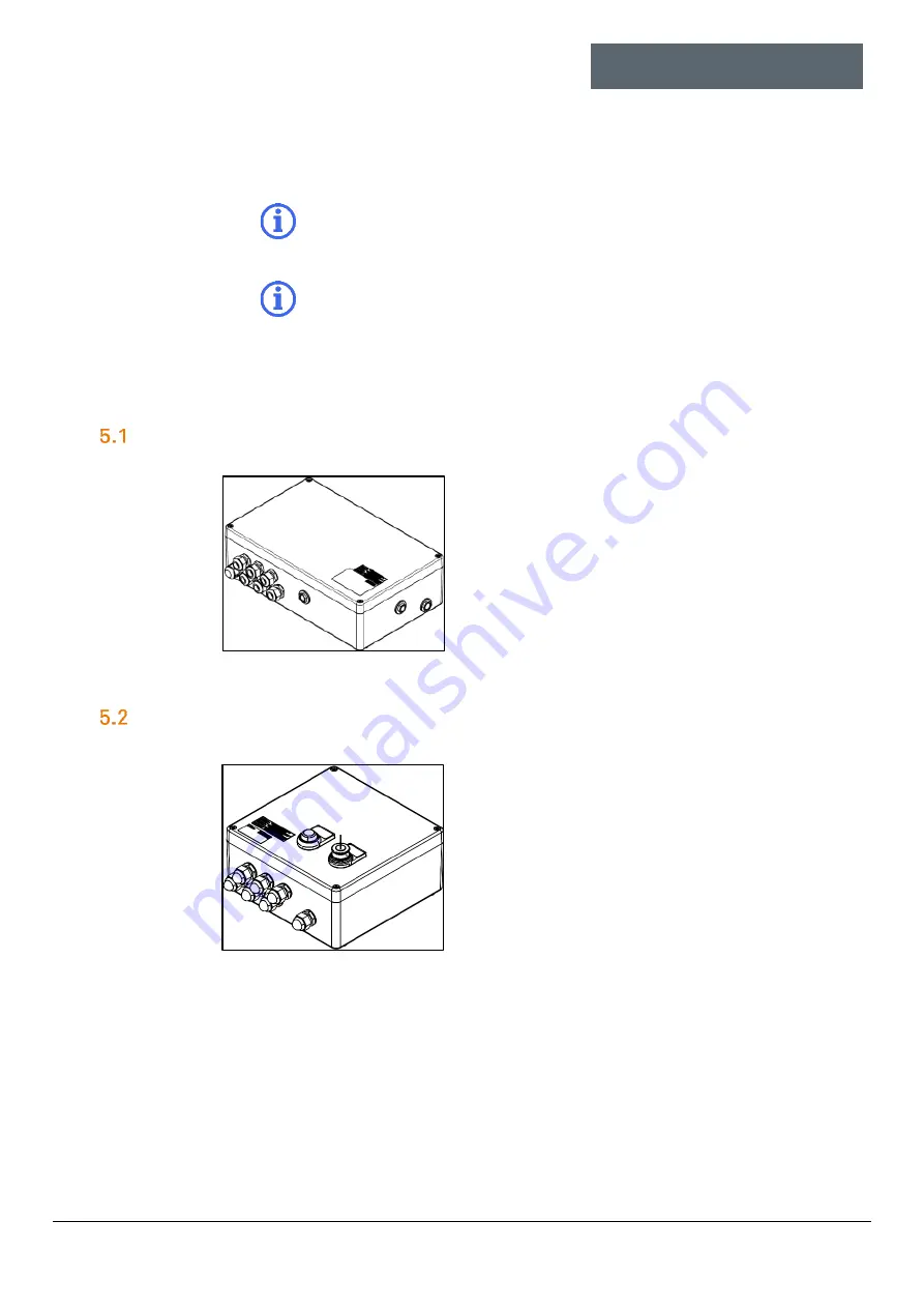
Installation of the Ex p control unit, type 07-37A2-3211/2726
Install the Ex p control unit at the intended position
using the fixing options on the enclosure.
M6 screws with corresponding locking elements
can be used as fixing material.
The accompanying drilling pattern is provided in the
Appendix.
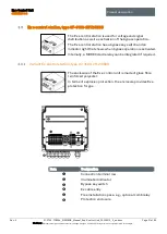
Installation of the Ex e control station, type 07-3103-2512/0639
Install the Ex p control unit at the intended position
using the fixing options on the enclosure.
M6 screws with corresponding locking elements
can be used as fixing material.
The accompanying drilling pattern is provided in the
Appendix.


