Bartec Ex p Control Unit APEX, Manual
The Bartec Ex p Control Unit APEX is a cutting-edge industrial control device designed for hazardous environments. Enhance workplace safety with this reliable control unit that delivers unparalleled performance and efficiency. Access the comprehensive user manual for free download from our website, ensuring a seamless installation and operation process.
Share
Download


Reviews:
No comments
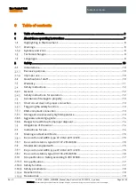
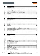
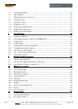
Related manuals for Ex p Control Unit APEX

HD Series
Brand: Hankscraft Runxin Pages: 53

EVI-D70
Brand: VADDIO Pages: 2

VLT AQUA Drive FC 202
Brand: Danfoss Pages: 124

AME 55
Brand: Danfoss Pages: 2

AME 110 NL
Brand: Danfoss Pages: 8

AK-CH 650
Brand: Danfoss Pages: 114

ECL Comfort 300
Brand: Danfoss Pages: 2

TS715Si
Brand: Danfoss Pages: 16

AME 438 SU
Brand: Danfoss Pages: 24

AK-LM 330
Brand: Danfoss Pages: 8

ECL Comfort 296
Brand: Danfoss Pages: 159

VLT AutomationDrive FC 301
Brand: Danfoss Pages: 78

AME 335
Brand: Danfoss Pages: 20

ECL Comfort 210
Brand: Danfoss Pages: 12

ECL Comfort 110
Brand: Danfoss Pages: 8

ECL Comfort 100M
Brand: Danfoss Pages: 21

AFQM
Brand: Danfoss Pages: 16

CCR2
Brand: Danfoss Pages: 64


