Commissioning
Ex p Control Unit
SIEMENS Set
Page 62 of 80
01-37A2-7D0004_SIEMENS_Manual_Exp-Control-Unit_20220216_0_en.docx
Rev. 0
Disclaimer: We reserve the right to make technical changes. Changes, errors and printing errors do not justify claims for damages.
Start up Ex p System
For the first commissioning of the SIEMENS set in connection with a SIEMENS
gas analyzer, proceed as follows.
Procedure:
The pneumatic tubing of the Ex p control unit is connected to the gas
analysis system as described in chapter 5.
The electrical wiring of the Ex p control unit is connected as described in
chapter 6.
Activate the Ex p control unit power supply
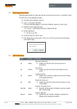
Status LED lights up
LED p2 lights up
Activate purge gas supply
The mounted pressure reducer is set to a minimum of 2 bar and a
maximum of 3 bar.
The purge gas entering via the operating flow causes a pressure increase
LED p2 goes off
LED p1 lights up green
The purge gas valve switches to purge
LED Operate flashes green
Purge time runs for 5 minutes
After the purge time has expired, the valve switches back to operating
flow
LED Operate lights up green
Operation SIEMENS analyzer is enabled
If the valve switches between the purge flow and the operating
flow, this is a sign that either the pressure reducer is set too low
or the leakage losses, e.g. through cable glands that are not
closed, are too high. If the leakage losses are too high and cannot
be compensated, the gas analyzer will not be released for
operation.
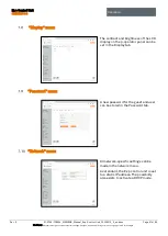
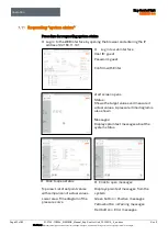
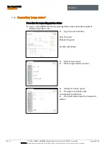
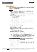
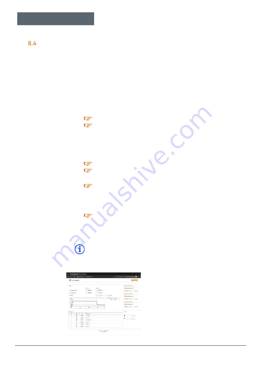
View of the sequence described above in the
WEB interface:
The sequence of the purging can be followed
in the web interface of the Ex p control unit.

