background image

ULTRASAMPLER® sample collection system 
150 

Measuring System MAK TIGER 3003 Service manual, SA 131128, 10.03.2020 

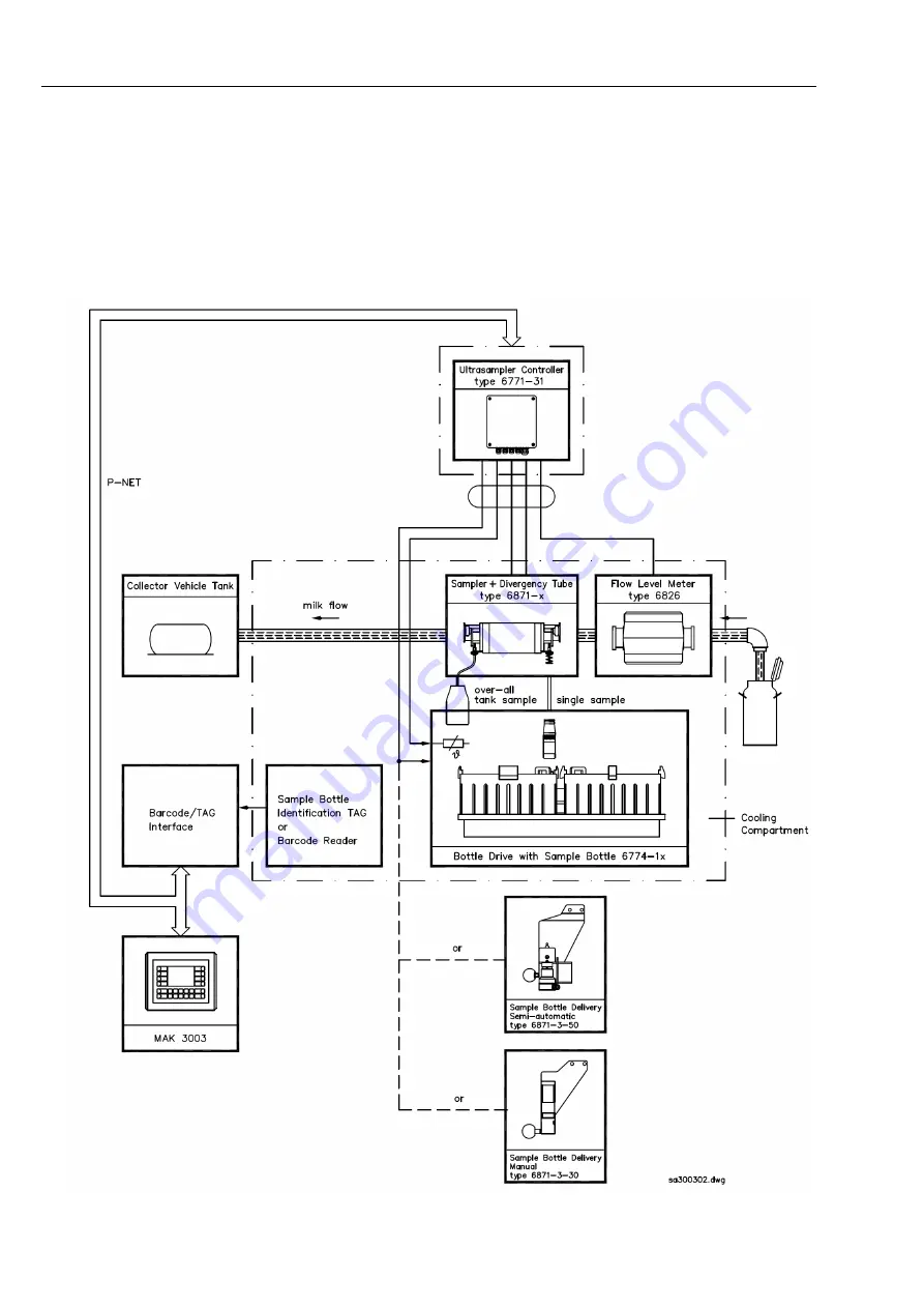
MAK 3003 matches the milk sample to the milk producer on the basis of the 
bar code or TAG, thereby ensuring that the data will be correctly attributed 
for the subsequent laboratory analysis. 
 
Fig. 2 illustrates the flow of the data signals and control signals between the 
functional units of the ULTRASAMPLER and MAK 3003. 


Summary of Contents for MAK TIGER 3003

Page 1: ...ENKE GmbH Schulstra e 30 D 94239 Gotteszell Phone 49 0 9929 301 0 Fax 49 0 9929 301 112 E Mail gotteszell bartec benke de Internet www bartec benke de Measuring System MAK TIGER 3003 Service manual SA...

Page 2: ...e without prior notice No part of this document may be reproduced processed or distributed in any form or by any means without the prior written permission of BARTEC BENKE Copyright 2020 by BARTEC BEN...

Page 3: ...termination terminal resistor Series C 16 4 6 5 Serial interfaces 16 4 6 5 1 Motherboard without CAN Bus 16 4 6 5 2 Motherboard with CAN Bus 17 5 Measuring system MAK TIGER 3003 18 5 1 Introduction 1...

Page 4: ...th large sample compartment 55 6 5 Pneumatic diagram 57 6 6 Electrical installation 58 6 6 1 Overview plan 58 6 7 Overview of control cabinet 59 6 8 Connection diagram for control cabinet 61 6 9 Termi...

Page 5: ...al data 99 16 2 Dimensions 102 16 3 Assembly installation 103 16 4 Wiring 106 16 5 Maintenance and servicing 106 17 V2000 Modul type 6757 14 Ser A 107 17 1 Technical data 108 17 2 Connection scheme 10...

Page 6: ...R 151 26 2 ULTRASAMPLER Controller type 6771 31 153 26 2 1 Technical data 153 26 2 2 Dimensions 154 26 2 3 Block diagram 155 26 2 4 Terminal connection plan 157 26 2 5 Wiring 159 26 3 Flow Level Meter...

Page 7: ...bution of PNET address system 3003 and 3002 196 27 3 Setting adjustment instructions 197 27 3 1 Correct installation 197 27 3 2 Initial operation 197 28 MAK TIGER 3003 Measuring System seal diagram 20...

Page 8: ...liability for any damage resulting from non observance of the safety regulations or from non compliance with the operating instructions or operating conditions Secondary da mage is excluded from the...

Page 9: ...ulting from the use operation or application of this user manual Please read the operating instructions carefully before using the prod uct Signs and symbols The following characters and symbols are u...

Page 10: ...ance with the applicable regulations and left the factory in perfect condition The units must be installed and serviced by duly skilled and qualified personnel Make sure that the information and opera...

Page 11: ...interference suppressor diode 2 3 Wiring instructions The wiring must be undertaken by trained professionals The installation must be carried out in accordance with the relevant na tional regulations...

Page 12: ...cator for signs of discolouration Check pressure setting on service units Change sampler hoses At least every 10 days Check intake strainer Monthly Check hydraulic oil cooler for excessive levels of...

Page 13: ...Safety precautions 5 Measuring System MAK TIGER 3003 Service manual SA 131128 10 03 2020...

Page 14: ...ram measuring system MAK TIGER 3003 Measuring System TIGER Type 6905 10 Printer Type 6761 11 ULTRASAMPLER Controller Type 6771 31 Bottle Drive Type 6774 10 or Type 6774 12 GPS Receiver Type 6722 18 Em...

Page 15: ...V Bordnetz load dump firm stabilised CPU Processor PowerPCTM MPC8270 266MHz Hard coded memory FLASH 256 MB FLASH programm memory SDRAM 128 MB SDRAM random accsess memory SRAM 4 MB battery backed power...

Page 16: ...max 100 Imp s Input optically isolated 5 k pull up Interface Interface printer RS 232 RxD TxD CTS RTS 115 K galvanically isolated Interface Fieldbus P NET RS485 76800 baud galvanically isolated Inter...

Page 17: ...Compact Controller TIGER Type 6942 10 Serie C 9 Measuring System MAK TIGER 3003 Service manual SA 131128 10 03 2020 4 2 Dimensions Compact Controller...

Page 18: ...pply outputs 9 12 terminals 76 83 SI 15 5 A UB_13 16 Supply outputs 13 16 terminals 84 91 SI 18 3 A 24V_COM RS 485 GPS printer P Net SI 20 1 A 24V_GPRS Supply for GPRS modem SI 25 3 A PWM out Control...

Page 19: ...s 13 16 terminals 84 91 SI 16 3 A 24V_COM RS 485 GPS printer P Net RS 232 CAN Bus SI 18 1 A 24V_GPRS Supply for GPRS modem SI 23 3 A PWM out Control of rotary pump terminals 92 93 LED displays Status...

Page 20: ...K TIGER 3003 Service manual SA 131128 10 03 2020 LED 99 Controller KCAN Flashes LED CPU Top Supply voltage Lights up LED CPU Bottom Busy Flashes 4 4 Compact Flash card Attention Make sure the equipmen...

Page 21: ...n be loaded from the CompactFlash card onto the new motherboard Only if the calibration switch is closed will the calibration parameters not be loaded and will then have to be adjusted To change the m...

Page 22: ...0 Serie C 14 Measuring System MAK TIGER 3003 Service manual SA 131128 10 03 2020 4 6 Compact Controller wiring Note Note Connections to external sources of voltage must be isolated Plus and minus con...

Page 23: ...nsor transfer pumping 5 n L Standby operation on 22 n L Group signal overfill monitor 51 n L Start button optional 52 n L Stop button optional 4 6 3 Outputs The outputs are user configurable The follo...

Page 24: ...n activated or terminating resistors switched on Attention CAN bus line It should be used a bus line which is isolated twisted and compliant to the CAN system e g UNITRONIC BUS CAN 1x2x0 5 mm CAN bus...

Page 25: ...20 4 6 5 2 Motherboard with CAN Bus Designation Terminals Interface on the system GPRS White plug dev usb ttyUSB0 Bluetooth Display connector dev usb ttyUSB1 GPS 4 7 dev ttyS3 not changeable Printer 8...

Page 26: ...res the air content which inevitably develops during milk collection and calculates it accordingly This creates a very efficient intake situation as the previously limiting element the gas separator i...

Page 27: ...he flow Particularly on the suction side the piping system including the sampler and the flowmeter has to be carried out continuously in min 3 to prevent pressure drops To maximize the transfer pump p...

Page 28: ...l min The pneumatic supply must be designed for 600 nl min The oils and antifreeze agents used in the pneumatic system incl compressor must be safe for use in food production processes For the electro...

Page 29: ...intake conditions max 2000 l min during pumping Drive Hydraulic motor 23 7 cm Flow rate of hydraulic oil about 40 l min 200 bar Speed about 1500 revs min Hydraulic connection Forward side 16 mm Retur...

Page 30: ...Measuring system MAK TIGER 3003 22 Measuring System MAK TIGER 3003 Service manual SA 131128 10 03 2020 5 5 Piping diagram...

Page 31: ...Measuring system MAK TIGER 3003 23 Measuring System MAK TIGER 3003 Service manual SA 131128 10 03 2020...

Page 32: ...Measuring system MAK TIGER 3003 24 Measuring System MAK TIGER 3003 Service manual SA 131128 10 03 2020...

Page 33: ...hielding plates see 4 4 Suggested design Its minimum volume has to be 60 liters and it should rather be dimensioned too large than too small For the design of the con tainer directive 2009 105 EC rela...

Page 34: ...Measuring system MAK TIGER 3003 26 Measuring System MAK TIGER 3003 Service manual SA 131128 10 03 2020 5 6 1 Measurement system basic set front view Optional DN 100...

Page 35: ...stem MAK TIGER 3003 27 Measuring System MAK TIGER 3003 Service manual SA 131128 10 03 2020 5 6 2 Measurement system basic set side view 5 6 3 Measurement system basic set top view Optional DN 100 Opti...

Page 36: ...Measuring system MAK TIGER 3003 28 Measuring System MAK TIGER 3003 Service manual SA 131128 10 03 2020 5 6 4 Ejector unit...

Page 37: ...Measuring system MAK TIGER 3003 29 Measuring System MAK TIGER 3003 Service manual SA 131128 10 03 2020 5 7 Pneumatic plan BARTEC BENKE delivery scope...

Page 38: ...he ejector control valve the ejector and the V3 V5 and V10 valves to ensure that they are all working correctly This is simply done by vacuum testing Any components showing signs of abnormality heavy...

Page 39: ...nnection 25 pole cable Ambient conditions Operating temperature 5 50 C Protection class IP 65 Mechanical data Housing specification PPA copolymer Dimensions excluding silencer and sealing plug 127 2 x...

Page 40: ...Filter regulator Order no 301644 5 9 1 Technical data Device specific data Operating pressure Max 12 bar Adjustment range 0 3 to 10 bar Air connections IG 1 4 Ambient conditions Operating temperature...

Page 41: ...g heavy duty filter Order no 292870 5 10 1 Technical data Device specific data Operating pressure Max 12 bar Adjustment range 0 3 to 10 bar Air connections 8 mm Filter unit 0 01 m Ambient conditions O...

Page 42: ...ata Device specific data Operating pressure Max 7 5 bar typ 5 6 bar Compressed airflow 430 Nl min 5 6 bar Air connection 12 mm Ambient conditions Operating temperature 20 80 C Mechanical data Housing...

Page 43: ...1 Technical data Device specific data Operating pressure Max 7 bar Air connection IG 1 8 Ambient conditions Operating temperature 20 80 C Mechanical data Housing specification Epoxy resin powder coat...

Page 44: ...evice specific data Operating pressure Max 7 bar Air connection IG 1 8 Ambient conditions Operating temperature 20 80 C Mechanical data Housing specification Epoxy resin powder coated Weight 0 70 kg D...

Page 45: ...hnical data Device specific data Operating pressure Max 7 bar Air connection IG 1 8 Ambient conditions Operating temperature 20 80 C Mechanical data Housing specification Epoxy resin powder coated Wei...

Page 46: ...6980 101 Order no 293901 5 15 1 Technical data Electrical data Operating voltage 24 30 V DC on board power supply Supply line Min 2 5 mm Ambient conditions Operating temperature 20 50 C Storage temper...

Page 47: ...Measuring system MAK TIGER 3003 39 Measuring System MAK TIGER 3003 Service manual SA 131128 10 03 2020 5 15 2 Dimensions...

Page 48: ...ice manual SA 131128 10 03 2020 5 16 Suggested design of vacuum container Not included in BARTEC BENKE delivery scope Note Fasten the vacuum container via vibration decoupling rubber damper Cut milk s...

Page 49: ...Measuring system MAK TIGER 3003 41 Measuring System MAK TIGER 3003 Service manual SA 131128 10 03 2020 5 16 1 Suggested dimensions of vacuum container...

Page 50: ...Measuring system MAK TIGER 3003 42 Measuring System MAK TIGER 3003 Service manual SA 131128 10 03 2020 5 16 2 Dimensions of measurement system with suggested design Mak Tiger 4Zoll kpl jpg...

Page 51: ...Measuring system MAK TIGER 3003 43 Measuring System MAK TIGER 3003 Service manual SA 131128 10 03 2020 5 17 Overview of the hydraulic...

Page 52: ...Measuring system MAK TIGER 3003 44 Measuring System MAK TIGER 3003 Service manual SA 131128 10 03 2020 5 17 1 Connection of hydraulic system to control block 303148 pdf Pressure connection Return flow...

Page 53: ...of the desired mounting opening and screw in the proximity switch to the stop Then turn it back by approx 0 75 to maximally 1 rotation and lock it with both nuts If there is no signal screw the proxim...

Page 54: ...ump incl control block 303148 Seal kit for Packo pump MCP2 65 250 371308 Welding socket 292938 Gear motor for control block LT 30X44 1 K 367480 Seal kit Gear Motor LT 30X44 1 K 307788 Ball valve 33512...

Page 55: ...Measuring System MAK TIGER 3003 Service manual SA 131128 10 03 2020 5 19 Electrical installation 5 19 1 Overview diagram Note IMPORTANT Mount GPS and modem antenna at the highest point of the truck w...

Page 56: ...et cassette Signal M Inlet motor of inlet cassette Signal M star motor of star wheel drive Signal P star self holding contact for star wheel drive Ground reference potential for signal P star Signal P...

Page 57: ...p UP DOWN 8 3 83 Bottle transport 9 4 84 Magnetic plate motor 10 Reference ground for OUT 1 4 11 5 12 6 13 7 14 8 15 Reference ground for OUT 5 8 5 19 5 Terminal connections of Bottle Drive Schwarte M...

Page 58: ...Measuring system MAK TIGER 3003 50 Measuring System MAK TIGER 3003 Service manual SA 131128 10 03 2020 5 19 6 Wiring of Emergency operation unit...

Page 59: ...rate without gas separators The latest sensor technology is used to measure the air portion which una voidably occurs during intake and offsets it accordingly This significantly increases the efficien...

Page 60: ...stantial influence on the performance of the measuring system Some comments on this If possible avoid Changing the cross sectional area Sharp elbows Right angled outlets T pieces Inward protruding wel...

Page 61: ...d air supply must be sufficient 500 nl min at at least 7 bar to guarantee the supply of compressed air or an electrical auxiliary compressor must be installed A power supply of at least 16 A CEE must...

Page 62: ...Measuring system MAK E TIGER 3003 54 Measuring System MAK TIGER 3003 Service manual SA 131128 10 03 2020 6 4 Measuring system 6 4 1 Pipework diagram...

Page 63: ...easuring system MAK E TIGER 3003 55 Measuring System MAK TIGER 3003 Service manual SA 131128 10 03 2020 6 4 2 Dimensions of measuring system with large sample compartment Measuring system frontal view...

Page 64: ...Measuring system MAK E TIGER 3003 56 Measuring System MAK TIGER 3003 Service manual SA 131128 10 03 2020 Measuring system side view Measuring system plan view...

Page 65: ...TIGER 3003 57 Measuring System MAK TIGER 3003 Service manual SA 131128 10 03 2020 6 5 Pneumatic diagram BARTEC BENKE scope of delivery For information about the pneumatic system see Chapter 5 7 1 Ele...

Page 66: ...asuring System MAK TIGER 3003 Service manual SA 131128 10 03 2020 6 6 Electrical installation 6 6 1 Overview plan Note IMPORTANT GPS and modem antenna must be installed at the highest point of the sys...

Page 67: ...Measuring system MAK E TIGER 3003 59 Measuring System MAK TIGER 3003 Service manual SA 131128 10 03 2020 6 7 Overview of control cabinet...

Page 68: ...Measuring system MAK E TIGER 3003 60 Measuring System MAK TIGER 3003 Service manual SA 131128 10 03 2020 Left side Front Right side...

Page 69: ...Metro Shield 24x2 5 mm shield 2A1 shield Control line FC bk 2A1 18 X5 1 br 2A1 5 X5 15 rd or 2A1 29 X5 3 yl 2A1 2 X5 14 gn 2A1 6 X5 5 bl 2A1 20 X3 3 vl 2A1 54 X5 6 gr 2A1 19 X5 2 wt 2A1 33 X3 2 wtbk...

Page 70: ...eld 8X1 shield Ethernet connection wtor 8X1 1 or 8X1 2 wtgn 8X1 3 bl 8X1 4 wtbl 8X1 5 gr 8X1 6 wtbn 8X1 7 bn 8X1 8 W20 LiYCY 7x0 25 DIN47100 Shield 7x0 25 mm shield PNET barcode reader unit wt bn 9A1...

Page 71: ...105 AW G20 24x0 5 AWG Metro Shield 24x2 5 mm shield Valve compact controller bk 5A1 19 8A1 80 br 5A1 12 8A1 20 rd 5A1 39 8A1 78 or 5A1 16 8A1 28 yl 5A1 14 8A1 24 gn 5A1 13 8A1 22 bl 5A1 17 8A1 76 vl 5...

Page 72: ...easuring System MAK TIGER 3003 Service manual SA 131128 10 03 2020 W107 lflex 400 P 1 2x1 5 mm X3 18 6S1 1 Thermostat for ejector hea ter 2 X3 19 6S1 2 W108 lflex 400 P 1 2x1 5 mm X3 20 6E1 1 Ejector...

Page 73: ...Measuring system MAK E TIGER 3003 65 Measuring System MAK TIGER 3003 Service manual SA 131128 10 03 2020 6 9 Terminal assignments for compact controller...

Page 74: ...7 Digital output OUT 8 Reference ground for OUT 5 8 X5 1 X5 2 X5 13 X5 8 As required As required As required As required As required As required As required As required As required As required 16 17...

Page 75: ...6 47 48 49 50 51 Signal M Up bottle lifting motor Signal M Down bottle lifting motor Signal M Out magazine discharge motor Signal M In magazine infeed motor Signal M Star star drive motor Signal P Sta...

Page 76: ...nit Valve terminal 6 bar service unit Compressed air level 4 bar service unit filter 0 01 Air consumption ejector approx 500 nl min 5 6 bar Suction power type 1300 l min under good intake conditions S...

Page 77: ...Measuring system MAK E TIGER 3003 69 Measuring System MAK TIGER 3003 Service manual SA 131128 10 03 2020 6 12 Three dimensional illustration...

Page 78: ...x 380 440 V Overload 1 x 380 440 V 14 4 A 15 8 A Output current Continuous operation 3 x 380 440 V Overload 3 x 380 440 V 16 A 17 6 A Ambient conditions Min ambient temperature under full load 0 C Min...

Page 79: ...Iout N 150 min 5 s Output current 30 A 70 C 40 A 60 C 48 A 45 C Efficiency 93 7 3 400 V AC 93 5 3 480 V AC Ambient conditions Relative humidity 5 95 condensation not permitted Temperature range 40 to...

Page 80: ...ry undervoltage and overvoltage A change over contact is used for the alarm or disconnection in the event of power failures voltage or asymmetry the second change over contact only responds to an inco...

Page 81: ...trical data Rated control supply voltage Us 160 690 V Rated frequency 50 60 Hz Ambient conditions Permissible ambient temperature during operation during storage 25 to 60 C 40 to 85 C Connection type...

Page 82: ...tact closes is in relation to the rise in temperature The NC contact for the heater opens and the NO contact for the fan closes when the specified value is exceeded Electrical data Number of contacts...

Page 83: ...h Air flow rate in combination PF PFA 30 000 IP55 55 64 m h Ambient conditions Noise level according to EN ISO 3741 IP55 40 dB A Temperature range 40 to 55 C Protection class according to EN 60529 UL...

Page 84: ...Service manual SA 131128 10 03 2020 6 13 4 3 Control cabinet heater S no 395023 Electrical data Voltage 24 V DC Power 150 W Ambient conditions Connection Silicone cable 3 x 0 75 mm Protection type IP5...

Page 85: ...x permissible operating voltage 48 V AC DC Max permissible current per branch 1 A Max permissible current all branches 4 A Pole number 8 Installation position any Connection data Connection 1 Connecti...

Page 86: ...03 2020 Mechanical data Dimensions W x H x D 26 9 x 69 x 62 mm Pin assignment according to TIA 568B Terminal Wire colour 1 white orange 2 orange 3 white green 4 blue 5 white blue 6 green 7 white brow...

Page 87: ...and cleanable with compressed air Ventilation hot side 1x compact fan installed internally speed regulated Protection class IP67 Ventilation cold side 1x compact fan installed internally Protection cl...

Page 88: ...sing the Enter key and holding it down for approx 15 seconds After the temperature is saved the display automati cally jumps to the current temperature display To adjust the hysteresis delivery state...

Page 89: ...nt without IO link 250 mA Measuring range Absolute pressure 0 16 bar Process connection Internal thread 1 4 inch Electrical connection Round plug connector M12x1 4 pole Ambient conditions Permissible...

Page 90: ...m cable wire end ferrules Milk sensor output Positive switching DC 24 V impulse current 20 mA Milk sensor alternating voltage 12 V AC approx 1 5 kHz Milk sensor switching threshold Approx 500 Ambient...

Page 91: ...light coating of grease to O ring D 12 0 x 3 0 VMQ 70 FDA Best Nr 335326 attached to temperature probe insert it in the welded nipple and using a fingertip fit it carefully in the O ring groove at th...

Page 92: ...be shortened to any length 8 1 Technical data Electrical Data Operating voltage DC 24 V 10 20 50 mA Connection Cable 5 m conductor and sleeves Output milk sensor Plus switching DC 24 V Switching curr...

Page 93: ...t the front end Adjust and use fingertip to check that it is seated evenly Using a hacksaw carefully cut the electrode rod on the milk sensor to the required length and strip the isolation approx 1 5...

Page 94: ...uxiliary power DC 24 V 10 20 50 mA Connection type 5 m cable wire end ferrule Milk sensor output Positive DC 24 V Switching current 20 mA Milk sensor switching threshold Approx 500 Milk sensor alterna...

Page 95: ...ing of grease to O Ring D 12 0 x 3 0 VMQ 70 FDA Best Nr 335326 attached to temperature probe insert it in the welded socket and using a fingertip fit it carefully in the O ring groove at the front end...

Page 96: ...nal output span 10 1 Technical data Elektronical data Auxiliary energy DC 24 V 10 20 50 mA Connection type Cable 5 m wire end ferrule Output U_Milk Analog 0 0 2 1 V Measuring range 0 5 K Ambient condi...

Page 97: ...Milk sensor series B type 6703 15 89 Measuring System MAK TIGER 3003 Service manual SA 131128 10 03 2020 10 2 Dimensons...

Page 98: ...the O ring groove at the front end Check correct even fit by fingertip scanning Carefully cut the electrode rod of the milk sensor with an iron saw to the required length without damaging the insulati...

Page 99: ...gnal 4 20 mA Measuring range 1 2 bar Connection 2 wire Ambient conditions Fluid temperature 20 90 C Operating temperature 20 80 C Mechanical data Housing specification Nickel chromium steel 1 4301 Spe...

Page 100: ...ted conditions 23 C 2 C 1 013 hPa Other machine related data Flow calming section 5 x nominal diameter Electrical data Auxiliary power DC 24 V 5 50 mA Connection type Cable approx 7 m Inputs and outpu...

Page 101: ...Bubble Sensor 3 series A type 6900 17 93 Measuring System MAK TIGER 3003 Service manual SA 131128 10 03 2020 12 2 Dimensions...

Page 102: ...ted conditions 23 C 2 C 1 013 hPa Other machine related data Flow calming section 5 x nominal diameter Electrical data Auxiliary power DC 24 V 5 50 mA Connection type Cable approx 7 m Inputs and outpu...

Page 103: ...eries A type 6900 19 95 Measuring System MAK TIGER 3003 Service manual SA 131128 10 03 2020 13 2 Dimensions Note Please take into account when installing the sensor that the open ends of the electrode...

Page 104: ...0 111 Order no 308328 14 1 Technical data Electrical data Output current 4 20 mA Supply voltage DC 24 V 4 V Connection 5 m cable wire end ferrules Ambient conditions Operating temperature 40 80 C Mech...

Page 105: ...nnection M12 plug 4 pole Ambient conditions Operating temperature 40 70 C Storage temperature 40 85 C Medium temperature 10 140 C 143 C max 120 Min Mechanical data Housing specification Stainless stee...

Page 106: ...Level sensor without float type 6900 113 98 Measuring System MAK TIGER 3003 Service manual SA 131128 10 03 2020 Dimensions of level sensor...

Page 107: ...sure range 100 l min to 2000 l min depending on version see table Accuracy 0 3 In the above measuring range Conductivity 5 S cm Pressure max 10bar Electrical Data Auxiliary voltage 24V DC 15 Power con...

Page 108: ...nel 120 3 4 Phase 1 Error Phase 1 18 17 Error Phase 1 Phase 2 16 17 UP DOWN Phase 2 Phase 3 Ambient conditions Admissible operating temperature 10 50 C Admissible storage temperature 10 50 C Protectio...

Page 109: ...50 l D A CH 6823 5 215774 NW 2 5 83 l min 1167 l min 50 l NL 6823 6 242839 NW 3 50 l min 2000 l min 100 l NL 6823 9 1 247093 NW 3 100 l min 1400 l min 200 l D 6823 9 2 301246 NW 3 200 l min 2000 l min...

Page 110: ...Flow Meter MID type 6823 x 102 Measuring System MAK TIGER 3003 Service manual SA 131128 10 03 2020 16 2 Dimensions electrodes Top view...

Page 111: ...flowmeter can be mounted in the flow direction rising 15 to 90 The position of the EMF must be chosen so that it is always filled with liquid in stalled after the air separator and at the point with...

Page 112: ...direction of flow Position at which the MID is always filled with liquid Reduce amount of gas in the liquid to a minimum as entrained air can also affect the flow measurement Therefore install the flo...

Page 113: ...pe connections from the MID Attention Do not lose the seals and put them back carefully when reassembling First screw the threaded milk pipe adapters with the union nuts on both sides of the pipe conn...

Page 114: ...ing MID wired with P NET pulse output connection and display unit connection 16 5 Maintenance and servicing The usual cleaners approved for use with food in the dairy industry can be used to clean the...

Page 115: ...System MAK TIGER 3003 Service manual SA 131128 10 03 2020 17 V2000 Modul type 6757 14 Ser A Order No 279051 The V 2000 module type 6757 14 Ser A forms the heart of the control unit with power unit for...

Page 116: ...ion Quantity 2 x 4 Galvanic isolation Optocoupler 2500 VRMS Frequency Max 10 kHz Switching level 0 24 V on boarder supply system Current per output 1A DC short circuit proof Switch type High side soli...

Page 117: ...V2000 Modul type 6757 14 Ser A 109 Measuring System MAK TIGER 3003 Service manual SA 131128 10 03 2020 17 2 Connection scheme Front Back...

Page 118: ...V pk 508 GND ye 509 In Signal S1 gy 510 24V pk 511 GND ye 512 In Signal S2 gy 513 24V B 514 IN1 Signal 515 516 24V B 517 IN2 Signal 518 519 24V B 520 IN3 Signal 521 522 24V B 523 IN4 Signal 524 525 Si...

Page 119: ...V2000 Modul type 6757 14 Ser A 111 Measuring System MAK TIGER 3003 Service manual SA 131128 10 03 2020 Schirm pk gy S Bbn B gn A ye GND GND RxD RxD TxD TxD...

Page 120: ...V2000 Modul type 6757 14 Ser A 112 Measuring System MAK TIGER 3003 Service manual SA 131128 10 03 2020 17 3 Pipeline scheme...

Page 121: ...urrent consumption 100 mA Interface RS 485 Baud rate 9600 bit s Cable length 11 8 m Connection Cable 6 wire shielded Protocol ISO 15693 Frequency 13 56 MHz Read write distance Direct coupling Ambient...

Page 122: ...TAG Reader 13 56 MHz Type 6910 15 114 Measuring System MAK TIGER 3003 Service manual SA 131128 10 03 2020 18 2 Dimensions and connection Connection Colour Signal rd 24V bu 0 V ye B gn A...

Page 123: ...e reading unit is set at the factory to read bar codes of the Inter leaved 2 of 5 type with the mandatory 10 characters The default operating mode is continuous scanning 19 1 Technical data Electrical...

Page 124: ...o major vibrations near the bar code reader taking due account of the length of its cable It must be possible to attach the connection leads in the bar code reader unit when installed Installation Aff...

Page 125: ...ating voltage pk gy wh 24 V Operating voltage Shield OUTPUT SIDE Signal Designation Terminal Wire colour HZG_24V Bar code reader heating 24 V type 6727 40 12 ye HZG_24V Constant current source KS_RT T...

Page 126: ...reconfigured Fault may need to be read out via P NET service channel P NET P NET ON LED flashes via P NET on the bar code reading unit on write access or read access LED off Bar code reading unit is...

Page 127: ...ion 2 m connection cable with open ends closed with wire end ferrules cable inlet PG7 Output TTL compatible output bright low dark high Transmitter light Red light 900 nm Ambient conditions Operating...

Page 128: ...angles to the sample bottle axis a There should be a distance of approx 4 mm b between the bar code reader and the sample bottle A 4 mm hexagon wrench or the shank of a 4 mm twist drill are examples o...

Page 129: ...tputs 8 FET semiconductor outputs positive Electrical isolation of logic circuit and outputs via optocoupler Min switching current 100 A Max current per output at signal 1 1 A up to 60 C Total load ca...

Page 130: ...of housing 2 01 kg Weight of basic module 0 4 kg 4 mounting plates with oblong holes for M6 screw fittings I O box MAK plus 1 type 6753 51 I O box MAK plus 1 Optional add ons 1 x input extension modu...

Page 131: ...of housing 2 7 kg Weight of basic module 0 4 kg 4 mounting plates with oblong holes for M6 screw fittings I O box MAK plus 2 type 6753 61 I O box MAK plus 2 Optional add ons 1 x input extension modul...

Page 132: ...be configured via a switch on the right of the module Therefore the order in which the modules are positioned is important The basic module has the static address The address of every additional modul...

Page 133: ...ice manual SA 131128 10 03 2020 Output extension module 8D0 2 0A type 6753 112 Dimensions W x H x D 55 x 85 x 58 mm Power consumption logic circuit 0 325 W Weight 1 5 N 0 15 kg Max current per output...

Page 134: ...1 x 6 3 A 1 x 2 0 A 35 x 74 x 65 mm 0 75 N 75 g 1 x 6 3 A 1 x 2 0 A Order details Accessories replacements I O basic module 8DI 8D0 type 6753 110 276817 Input extension module 8DI type 6753 111 276819...

Page 135: ...mm x 195 mm x 148 mm Installation position Vertical or horizontal In case of vertical installation please note the in structions for attaching the correct labelling strip and changing the paper senso...

Page 136: ...r vertical installation a Install the printer so that the paper comes out at the top and the cable connection is facing down b The labelling strip for feed button and LEDs is upside down in this posit...

Page 137: ...stallation dimensions for bracket in case of vertical installation 1 Fit retaining plate 3 Fit printer by screw plates in retaining plate A 2 Fit screw plates on printer a Affix the top plate through...

Page 138: ...l of paper so that the printer can continue printing When this LED flashes it indicates standby status during the self test printout or during the execution of a macro if the execute macro command is...

Page 139: ...time the printhead may have overheated If the printhead has over heated the printer will continue printing as soon as the head has cooled down usually within two to three minutes If there is no paper...

Page 140: ...aper jam in the printer Caution The printhead can become very hot after prolonged continuous use Do not touch it 1 Follow the instructions below to clear a paper jam 2 Switch the printer off and press...

Page 141: ...uch as a drawing pin or paper clip has fallen into the cutter and caused a blockage the printer will be in error state and will auto matically start a recovery process If the problem is not serious th...

Page 142: ...itch on the power supply to the printer in order to start the self test The self test prints out the printer settings and then the following cuts off the paper and waits the PAPER OUT LED will flash S...

Page 143: ...rd font 5 x 7 35 characters per line Normal font 7 x 7 42 characters per line Wide font 5 x 7 17 characters per line Wide font 7 x 7 21 characters per line Line feed 4 2 mm Printing procedure Needle p...

Page 144: ...ripple 150 mV eff Connection 25 pole socket RS 232 3 pole plugs power supply DC 24 V Ambient conditions Operating temperature 5 C 40 C Storage temperature 10 C 50 C Climatic class KYF Protective syst...

Page 145: ...279562 23 3 1 Printer mount connection Connection of printer mount without series Terminal Terminal connection Printer mount type 6961 100 8 24 V rd 9 RxD ye 10 11 TxD gn 12 13 GND bu Connection of p...

Page 146: ...tem MAK TIGER 3003 Service manual SA 131128 10 03 2020 DIP switch setting bottom Remove the adhesive label to change the DIP switch setting DIP switch no Printer mount type 6961 100 1 ON 2 OFF 3 ON 4...

Page 147: ...3 system 24 1 Technical data Electrical data Auxiliary power DC 6 40 V Typical power consumption 50 mA at DC 24 V Receiver aerial Inbuilt Interfaces RS 232 Electrical connection 5m of cable open wire...

Page 148: ...the product 130 mm of insulation stripped from cable end Assignment Signal DC 24 V GND Remote RxD TxD Colour Red Black yellow Blue White 24 1 3 Fitting The aerial is built into the receiver therefore...

Page 149: ...nna adapter and antenna are unearthed 25 1 GPRS Module Type 6942 100 Order no 290337 25 1 1 Technical data Operating voltage DC 5 36 V approx 83 mA at 24 V Dimensions 77 x 67 x 26 L x W x H Weight App...

Page 150: ...cover 2 Open the slot and insert the SIM card 25 2 Magnetic antenna Order no 360422 60mm H 13 mm Antenna length 5 m Attention Fit the antenna in a location with good reception The magnetic antenna ma...

Page 151: ...o 10 m Any measures to lengthen the cable must be avoided 25 3 1 Technical Data Operating voltage DC 5 36 V ca 83 mA bei 24 V Dimensions 77 x 67 x 26 L x B x H Weight Approx 90 g Mounting With two ova...

Page 152: ...PRS modem with Magnetic antenna 144 Measuring System MAK TIGER 3003 Service manual SA 131128 10 03 2020 25 3 3 Connection cable for 2 GPRS data modem Telit GT864 Quad type 4386 306 BNr 304946 L nge 10...

Page 153: ...003 Service manual SA 131128 10 03 2020 25 3 4 Dimensions and mounting Fit the modem in a dry dust free and dirt free area in a non hazardous area where it is not exposed to much vibration Dimensions...

Page 154: ...Connection from office to 3003 system HTTPS 443 Connection from 3003 system to office Ping Connection from 3003 system to office Additional options for office link up via FTL and FTP optional Service...

Page 155: ...ly automatic infeed systems for the empty sample bottles There are bar code and transponder TAG systems for the sample bottle identification The following units belong to the ULTRASAMPLER sample colle...

Page 156: ...The control unit is positioned at a suitable place near the sample collection system Systems with bottle drive for automatic sample bottle transport and sample bottle identification bar code or TAG a...

Page 157: ...is function is enabled then at the same time a branch in proportion to the volume will be taken into the tank sample bottle from every supplier on a round Operation with flow level meter If the ULTRAS...

Page 158: ...3003 matches the milk sample to the milk producer on the basis of the bar code or TAG thereby ensuring that the data will be correctly attributed for the subsequent laboratory analysis Fig 2 illustrat...

Page 159: ...sample collection A special rinsing process in the sampler before every sample collection pro cess largely prevents any residual milk in the sampling line from being car ried into the new sample bottl...

Page 160: ...ated in the milk pipeline upstream of the flow level meter with a minimum length of five times the nominal width If the system is operated without a flow level meter this flow calming section should b...

Page 161: ...not in operation the power supply must be interrupted Auxiliary energy electronics Operating voltage 24 V DC 16 35 V Current consumption 250 mA without stepper motors and load Fuse 1 A medium time la...

Page 162: ...face Protocol P NET Baud rate Adjustable 150 38 400 b s Galvanic separation None Maximum line length 2 30 m depending on baud rate Cable connection Clipped connection Ambient conditions Climate class...

Page 163: ...ULTRASAMPLER sample collection system 155 Measuring System MAK TIGER 3003 Service manual SA 131128 10 03 2020 26 2 3 Block diagram...

Page 164: ...se Si5 1 0 A Fuse Si6 10 A Fuse Si7 3 A Position of fuses on sampler circuit board Position of fuses Fusible cut out Si1 1 AM and fusible cut out Si2 3 15 AM can be ac cessed by opening the respective...

Page 165: ...required As required As required As required As required As required 16 17 18 19 Sampler motor for individual sample phase A Sampler motor for individual sample phase B Sampler motor for individual s...

Page 166: ...on board power supply for bottle drive Shielded connection for bottle drive channel bn rd ye gn pk vt gy wh Wire jumper bk bn wh Bottle drive Wires according to colour for type 6774 10 IN 7 terminal...

Page 167: ...5 Wiring Additional instructions for wiring 1 The outgoing wires from terminals 54 red 55 blue and 56 black on board power supply sampler motor voltage have to be connected to terminals 39 red 40 blu...

Page 168: ...ordance with direction given on the metal type plate direction Sensors Magneto inductive flow sensor with P controlled function monitoring measurement of filling degree via conductivity sensor Electri...

Page 169: ...76 NW 50 NW 65 Connecting flange connection via sealing ring and clamp in accordance with ISO 2852 NW 2 5 NW 76 Connecting flange connection via sealing ring and clamp in accordance with ISO 2852 NW 3...

Page 170: ...vel Meter 3 type 6826 30 302063 Mounting position Vertical mounting edgewise Flow Level Meter 2 90 type 6826 11 U950 17 682611 Flow Level Meter 2 5 90 type 6826 21 U950 17 682621 Flow Level Meter 3 90...

Page 171: ...laid flat or fitted upright depending on the design of the unit The milk pipe must always be horizontal Horizontal flat installation order Horizontal version Vertical upright installation order Vertic...

Page 172: ...screw the threaded milk pipe adapters with the union nuts on both sides of the pipe connections 3 Then fit the FLM not forgetting the flat gaskets 5 and secure with the fastening clamps 2 It might be...

Page 173: ...he diagram below Please follow the directions for use of the fol low on device when wiring 26 3 4 Electrical terminal assignment Terminal block Signal Colour 6771 31 3 Flow 4 20 mA bk 5 3 Flow 4 20 mA...

Page 174: ...ling cabinet monitoring sen sor Pt 100 optional Order no 216529 26 4 1 Technical Data Electrical data Measuring insert Pt 100 DIN EN 60 751 Tolerance class B Connection Four wire connection Ambient co...

Page 175: ...round magazines 26 5 1 Technical data Electrical data Auxiliary power DC 24 V Fuses No internal fuses fused via drive system Electrical connection Connector plug with inset socket F type Han 16 A 16 p...

Page 176: ...ULTRASAMPLER sample collection system 168 Measuring System MAK TIGER 3003 Service manual SA 131128 10 03 2020 26 5 2 Dimensions Mounting View from above...

Page 177: ...ULTRASAMPLER sample collection system 169 Measuring System MAK TIGER 3003 Service manual SA 131128 10 03 2020 View from the front...

Page 178: ...ULTRASAMPLER sample collection system 170 Measuring System MAK TIGER 3003 Service manual SA 131128 10 03 2020 View from the left View from below...

Page 179: ...n Installation Horizontal with reference to the position of the ULTRASAMPLER It must be possible to change the round magazines easily afterwards see diagram Connection Establish compressed air connect...

Page 180: ...ULTRASAMPLER sample collection system 172 Measuring System MAK TIGER 3003 Service manual SA 131128 10 03 2020 26 5 4 Wiring terminal assignment Wiring internally...

Page 181: ...ULTRASAMPLER sample collection system 173 Measuring System MAK TIGER 3003 Service manual SA 131128 10 03 2020 Terminal assignment...

Page 182: ...must be fused via drive system Pneumatic supply Plug in connections for pneumatic hose with 6 mm outer diameter Ambient conditions Operating temperature 10 C 50 C Storage temperature 10 C 70 C Protec...

Page 183: ...d the bottle transport cylinder must be retracted the star can be turned by hand counter clockwise If the cylinder is extended it clacks loud when turning the star counterclockwise 1 2 3 4 5 1 Bottle...

Page 184: ...ng position and settle the filled sample bottle with the aid of an operating lever The manual sample bottle lifting device is screwed onto the sampler and is mounted under the peristaltic pump In the...

Page 185: ...ty switch is to be connected to a device eg I O box 6753 with posi tive switching inputs this can be done by interposing the constant current module Type 6753 302 as a pull up between 24 V and the cor...

Page 186: ...mple collection system 178 Measuring System MAK TIGER 3003 Service manual SA 131128 10 03 2020 Picture 1 Controller Settings In the controller periphery the physical input used must be assigned the lo...

Page 187: ...ULTRASAMPLER sample collection system 179 Measuring System MAK TIGER 3003 Service manual SA 131128 10 03 2020 Dimensions...

Page 188: ...der the peristaltic pump In the filling position the injection needle of the sampler pierces the sealing plug of the sample bottle Two prox imity switches integrated in the lifting device detect the b...

Page 189: ...ntroller 1 MAK Compact Con troller 6942 10 I O Box 6753 Inputs brown bn IN 1 8 24 V blue bu IN 1 8 GND black bk Free inputs IN 1 8 Free inputs IN 1 8 Note If a ground switching proximity switch is to...

Page 190: ...mp 411 to clamp 407 GND Stabilization 12 V 24 V for magnetic disc motor type 6870 400 Barcode reader type 6727 40 The barcode reader is connected to the reading station Type 6723 10 The wiring and set...

Page 191: ...here must be space for the sampler and bottle drive in the sample collection box Fig 2 Fig 3 The bottle drive is seated horizontally in the sample collection box and also needs to be kept horizontal d...

Page 192: ...ULTRASAMPLER sample collection system 184 Measuring System MAK TIGER 3003 Service manual SA 131128 10 03 2020 Fig 2 Fig 3 Fig 2 and Fig 3 show the dimensions for the sampler and bottle drive lay out...

Page 193: ...for the branch pipe and flow level meter or must be assembled from individual pipe sections The exact position and length of the disconnection must be decided when the sample collection box is being d...

Page 194: ...ition Sampler and branch pipe Fitting the sampler on the branch pipe Attach the two sampler holders to the steel sections of the branch pipe from below Screw each of the holders onto the steel section...

Page 195: ...points Rough area pointing against the direction of milk flow rough area and opening of intake cannula pointing in the same direction The roughened surface is upright The roughened surface is flush w...

Page 196: ...nd remove branch pipe with or without sampler Installation of flow level meter type 6826 The flow level meter sits between the branch pipe of the sampler and the flow calming section and is mounted on...

Page 197: ...because of space constraints Screw down bottle drive with four M6 screws and protect screw fittings Loosen branch pipe fasteners Turn branch pipe with sampler until the tip of the injection needle is...

Page 198: ...e sampler type 6871 3 4 5 which is on the pump side The connection is made with two M8 x 15 pan head screws and lock wash ers The sampler can be fitted alone or connected to the branch pipe The sample...

Page 199: ...ing method Water bath circulated Cleaning the inside of the ULTRASAMPLER The parts requiring cleaning in this case are the surfaces in the branch pipe and in the flow level meter contacted by the milk...

Page 200: ...remove rotor protection Plexiglas Unscrew union nut on injection needle and intake cannula Take out old pump hose remove union nut Fitting the new pump hose NOTE Make sure that the new pump hose is n...

Page 201: ...manual SA 131128 10 03 2020 Continue turning the conveying wheel clockwise and fitting the pump hose until the pump hose is fully fitted in the groove Place union nut on pump hose Fit pump hose on int...

Page 202: ...10 3 Injektionsnadel montieren Disassembling the injection needle The injection needle and thumb wheel with thread for union nut form one unit Unscrew union nut and remove pump hose Remove pressure s...

Page 203: ...tem is wired correctly before switching on the wir ing system voltage 2 Set all the parameters on the Controller The menu structure of the config uration instructions can be followed It is not absolut...

Page 204: ...gister E8 342022 I O box 6753 110 Supplier sampler 3002 PNET address 35 H Supplier sampler 3003 PNET address 35 H Bar code reading station 6723 10 System 3002 PNET address 46 H System 3003 PNET addres...

Page 205: ...ed The sampler must be fitted at the highest point of the piping system to prevent milk residues from remaining in the system and affecting subsequent samples The injection needle must be positioned v...

Page 206: ...x throughput With pre rinse 20 l 200 l min 180 l min 40 l 400 l min 380 l min 80 l 800 l min 760 l min 160 l 1600 l min 1520 l min Note It is relatively difficult to operate the intake pump at differe...

Page 207: ...have been made to ascertain that the maximum ratings of the sampler are not being exceeded the electrical settings can be configured See configuration instructions 3003_TIGER_MAK_SAK_110625 pdf Standa...

Page 208: ...1 Take in a relatively large quantity 400 l without restricting the pump in take This quantity must accord with the default setting Step 2 Check whether the pumped sample bottle volume on the display...

Page 209: ...adjusted the pumped volume of the sampler should be about right even with small quantities If this is not the case however it is necessary to check whether the maximum limits of the sampler are being...

Page 210: ...ill auto matically be lower in fat This method is usually only effective with small quantities up to approx 100 l because with large quantities the remainder is not so heavily assessed as a percentage...

Page 211: ...e average fat levels were measured in the higher quantities 80 l and 160 l in the case of milk collection vehicles with high throughputs in con junction with the ULTRASAMPLER system therefore although...

Page 212: ...h GUIDE to calculating the correct settings All the correction factor settings need to be calculated with milk It is advisable to start with 20 for low and medium with the small intake quantities Afte...

Page 213: ...10 03 2020 28 MAK TIGER 3003 Measuring System seal diagram 28 1 Seal diagram for Compact Control ler type 6942 10 until series B Open position Access to measurement parameters Closed position No acces...

Page 214: ...l SA 131128 10 03 2020 28 2 Seal diagram for Compact Control ler type 6942 10 from series C Calibration switch Open Access to measurement parameters Closed No access to measurement parameters Sealed w...

Page 215: ...MAK TIGER 3003 Measuring System seal diagram 207 Measuring System MAK TIGER 3003 Service manual SA 131128 10 03 2020 28 3 Seal diagram for MID type 6823 x...

Page 216: ...Measuring System MAK TIGER 3003 Service manual SA 131128 10 03 2020...

Reviews: