background image

Summary of Contents for POLARIS 17-71V2 Series

Page 1: ...ugust 2019 Reservation 3 Technical data subject to change without notice Changes errors and misprints may not be used as a basis for any claim for damages Content Pages English 1 50 GmbH Max Eyth Straße 16 Phone 49 7931 597 0 Support support polaris bartec de 97980 Bad Mergentheim Fax 49 7931 597 119 Download http automation bartec de GERMANY Internet www bartec de ...

Page 2: ......

Page 3: ...POLARIS REMOTE for Zone 1 21 POLARIS Remote KVM Analog 15 19 1 Table of Contents Technical data subject to change 08 2019 ...

Page 4: ...Analog 10 4 1 1 General data 10 4 1 2 Characteristics POLARIS Remote KVM Analog 15 11 4 1 3 Characteristics POLARIS Remote KVM Analog 19 1 11 4 2 Keyboard 12 4 2 1 Explosion protection 12 4 2 2 General data 12 4 2 3 Characteristics enclosure for keyboard 13 4 3 Finger mouse trackball touchpad and joystick 13 4 3 1 Explosion protection 13 4 3 2 General data 14 4 3 3 Variants 14 4 4 Product labellin...

Page 5: ...4 Connection of STP cable 31 6 9 EMC Electromagnetic compatibility 32 6 9 1 Voltage supply AC and DC variants 32 6 9 2 Back up fuse 33 6 9 3 Interference suppression 33 6 9 4 Shielding 34 6 9 5 Connection of shielding 34 6 9 6 Examples of shielding connections 34 7 Commissioning 36 7 1 Final inspection 36 8 Operation 37 8 1 Putting into operation for the first time 37 8 1 1 Length adjustment POLAR...

Page 6: ......

Page 7: ...Blank ...

Page 8: ......

Page 9: ...e strict compliance with it is essential for safe installation and commissioning Accidents injuries and material damage can be avoided by circumspect handling and systematically following the instructions The examples tables and figures provided in this user manual are for illustration purposes Due to the different requirements of the respective application the BARTEC company cannot assume respons...

Page 10: ...GmbH also apply The current versions of the datasheets operating instructions certificates and EC declarations of conformity can be downloaded from www bartec de or may be requested directly from BARTEC GmbH 1 2 Handling the product The product described in these operating instructions has been tested and left the factory in perfect condition as regards meeting safety requirements To maintain this...

Page 11: ...with a dry cloth or cleaning it Do not open devices in a hazardous area The general statutory regulations or directives relating to safety at work accident prevention and environmental protection legislation must be observed e g the German industrial health and safety ordinance BetrSichV or the applicable national ordinances In view of the risk of dangerous electrostatic charging wear appropriate ...

Page 12: ... 5 Commissioning It must be checked that all components and documents are available before commissioning 1 7 Labelling test certificate and standards The device features an explosion protection label as well as a test certificate For an explanation of the symbols and information used see chapter 4 Technical data The POLARIS REMOTE KVM Analog series complies with Directive 2014 34 EU on equipment a...

Page 13: ...e assembly commissioning operation and maintenance Structural modifications without our prior authorisation Inadequate monitoring of components that are subject to wear Repairs done incorrectly Disasters due to the effects of foreign matter or Act of God events outside human control BARTEC grants a warranty period of one year on the POLARIS series starting from the BARTEC delivery date The warrant...

Page 14: ...easily and directly by means of the local unit already included in the scope of supply Illustration 2 e g local unit with STP cable The POLARIS Remote KVM Analog series is optimised for signals such as VGA and PS 2 USB via adapter A local monitor a keyboard and a mouse can be connected via VGA PS2 Out The touch screen is connected via an RS232 interface the installation of a driver is necessary an...

Page 15: ...th temperatures as low as down to 40 C we equip the POLARIS series with electrical heating On request we produce customised solutions with more command and signalling devices 2 2 System design 2 2 1 Standard Point to Point The voltage of the local unit is supplied via the PS 2 keyboard of the local computer A separate power pack is necessary in an individual case not contained in the scope of deli...

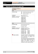
Page 16: ... T4 Gb Ex tb IIIC T120 C Db Certification IECEx IBE 11 0007X Standards in accordance with EMC Directive 2014 34 EU IEC 60079 0 2011 Edition 6 IEC 60079 1 2014 06 Edition 6 IEC 60079 5 2015 Edition 4 IEC 60079 7 2015 Edition 5 IEC 60079 11 2011 Edition 6 IEC 60079 18 2015 Edition 4 IEC 60079 28 2015 Edition 2 IEC 60079 31 2013 Edition 2 Special conditions The intrinsically safe circuits and the enc...

Page 17: ...DE GB06 B 00334 Korea KTL 14 KB4BO 0258X India CCEs P261984 China NEPSI GYJ18 1382X America CSA 70010166 More test certificates www bartec de EU conformity RoHS Directive 2011 65 EU Standards in accordance with EMC Directive 2014 30 EU EN IEC 61000 6 2 2005 EN 61000 6 4 2007 A1 2011 IEC 61000 6 4 2006 A1 2010 EN 60529 1991 A1 2000 A2 2013 IEC 60529 1989 A1 1999 A2 2013 Electrical safety EN IEC 610...

Page 18: ...le POLARIS Remote connection 1 x Ex e for STP S CAT 7 1 x Ex e power supply 2 x Ex i for PS 2 for intrinsically safe keyboard and mouse Optional interface modules 1 x Ex i Supply module for hand scanner Display Antireflection coating glass pane Optional touch screen Power supply AC 90 V to 253 V 10 50 Hz to 60 Hz DC 24 V 10 Max power consumption Pmax 100 W depending on the version Relative air hum...

Page 19: ... 50 C 0 C to 50 C Dimensions width x height x depth 411 mm x 332 mm x approx 135 mm Wall cut out width x height 394 5 mm x 315 5 mm 0 5 mm Weight approx 23 kg 4 1 3 Characteristics POLARIS Remote KVM Analog 19 1 Display 19 1 graphics capable TFT display SXGA resolution 1280 x 1024 pixels 16 2 million colours Brightness 300 cd m2 Visible surface approx 380 x 305 mm Contrast 1300 1 Backlighting LED ...

Page 20: ... Certification IECEx IBE 11 0007X Ex protection type Class I Zone 1 A Ex ib IIC T4 Gb Class II Zone 21 A Ex ib IIIC T120 C Db Certification CSA 15 70010166 More test certificates www bartec de 4 2 2 General data Construction Front panel fitting Material Polyester foil on aluminium sheet conditionally UV resistant Protection class front IP65 Dimensions width x height 420 mm x 170 mm Wall cut out wi...

Page 21: ...m Protection class IP65 Dimensions mm 4 3 Finger mouse trackball touchpad and joystick 4 3 1 Explosion protection Ex protection type ATEX II 2G Ex ib IIC T4 Gb II 2D Ex ib IIIC T120 C Db 20 C Ta 60 C 50 C Certification IBExU 05 ATEX 1117 X Ex protection type IECEx Ex ib IIC T4 Gb Ex ib IIIC T120 C Db Certification IECEx IBE 11 0007X Ex protection type Class I Zone 1 A Ex ib IIC T4 Gb Class II Zone...

Page 22: ...all Static Dynamic IP65 front site IP65 front site IP51 front site Dimensions width x height 130 mm x 170 mm Wall cut out width x height 100 mm x 140 mm Dimensions and wall cut out mm 4 3 3 Variants Finger mouse Type 17 71VZ 1000 Installation depth 15 mm Weight approx 270 g Touchpad Type 17 71VZ 2000 Installation depth 15 mm Gewicht approx 250 g Trackball Type 17 71VZ 3000 Installation depth 43 mm...

Page 23: ...POLARIS Remote KVM Analog 15 19 1 Technical data Technical data subject to change 08 2019 EN 15 48 4 4 Product labelling Example ATEX type label IMMETRO type label Warnings on the device Warning on terminal compartment Test sticker ...

Page 24: ... Intermediate storage ATTENTION Damage to property through incorrect storage Comply with the correct storage temperatures Keep the POLARIS free of moisture 5 3 Scope of delivery 1 x POLARIS Remote KVM Analog Zone 1 21 1 x Local Unit 1 x KVM cable optional serial cable for touch or hand scanner 1 x RJ45 network box 1 x RJ45 patch cable 3 m 1 x Reinforcement frame 1 x Set of mounting clamps 1 x User...

Page 25: ...spanner 7 mm POLARIS accessories 1 x socket wrench 5 5 mm System solution in an Exclusive II stainless steel enclosure e 1 x hex key 5 mm to fix the supporting system in place 5 4 1 Installation options The POLARIS can be installed directly in Enclosures Switch cabinet doors Operating consoles The POLARIS series are mounted by fitting them into front panels which can be done with very little effor...

Page 26: ...f from 0 C to 50 C and a relative air humidity of from 5 to 95 without condensation 6 1 Requirements The place where the POLARIS is installed must have sufficient mechanical stability fastening The enclosure intended for accommodating the POLARIS must be designed to bear the device s weight If a supporting system is used the surface underneath and the means of fastening the supporting system must ...

Page 27: ...onnel i e trained skilled specialists will have the necessary specialised know how to be able to perform all the mechanical work Familiarity with and the technically perfect implementation of the safety instructions described in this manual are preconditions for safe installation and commissioning 6 2 1 Installation in 2G 2D enclosure In order to guarantee the IP degree of enclosure protection IP5...

Page 28: ...maintenance of protection class IP65 POLARIS 15 05 0205 0009 POLARIS 19 1 05 0205 0010 Fit the reinforcement frame Illustration 6 Fixing reinforcement frame with mounting clamps to POLARIS Work steps 1 Insert the POLARIS into the cut out in the enclosure 2 From the back place the reinforcement frame over the POLARIS 3 Using the M4x12 2 screws to fasten the mounting clamps 1 to the rear side of the...

Page 29: ...ction of location CAUTION Pay attention to wall and ground condition A sufficiently stable wall e g concrete or limestone or floor e g concrete must be selected for securing the load bearing system The structural stability of the wall or floor must be able to bear 4 times the weight of the POLARIS as system solution The support arm system must be assembled using suitable mounting materials M12 e g...

Page 30: ...ical data subject to change 08 2019 6 2 3 Floor mounting Stainless steel enclosure Exclusive II Illustration 7 Drilling pattern supporting system for floor mounting 6 2 4 Wall mounting Stainless steel enclosure Exclusive II Illustration 8 Drilling pattern supporting system for floor mounting ...

Page 31: ...n lay the supply and data line s in the supporting system Make sure that your fingers do not get caught between the swivel adapter and the enclosure as you set up the POLARIS CSA approval The system solutions table mounting have not been tested and approved in accordance with CSA Must be checked separately in each individual case Illustration 9 Drilling pattern supporting system for table mounting...

Page 32: ...e installation of the intrinsically safe circuits The safety and accident prevention regulations applicable to the respective individual case must be observed Devices must be properly installed first before they may be operated It must be possible at all times to disconnect the devices from the voltage supply in fixed installations by means of an all pole mains isolating switch or fuse It must be ...

Page 33: ...re Do not open the locking screw DANGER Non certified cable glands and non sealed cable entries endanger the IP protection and accordingly the protection against explosions There is a risk of fatal injury in an explosive atmosphere Use Ex certified cable glands Close non sealed cable entries Illustration 10 Pin assignment POLARIS All connection screws and terminals in the terminal compartment must...

Page 34: ...f loosening Stainless steel enclosure Exclusive II Attach equipotential bonding to the enclosure All moving parts must be earthed Secure PE conductor connections against self loosening Work steps 1 Washer on to earthing stud 2 Push non sheathed cable with PE cable lug 1 on to earthing stud 3 Washer than Position spring washer 2 on threaded bolt and secure with hexagonal nut 3 max torque 2 9 Nm 4 L...

Page 35: ... of the approval The assembly instructions and installation conditions for the cable glands must be observed Tightening torque of cable glands Torque Connecting thread Nut non armoured cables 2 3 Nm 1 5 Nm armoured cables 8 Nm 5 Nm DANGER If the power supply is active there is a danger of life in an explosive atmosphere Disconnect the device before starting work from the voltage supply Only use ce...

Page 36: ...olour Color sequence according to DIN IEC 757 Terminal Colour Terminal Colour X13 WH OG T1 1 X14 OG R1 2 X15 WH GN T2 3 X16 GN R2 6 X17 WH BU T3 5 X18 BU R3 4 X19 WH BN T4 7 X20 BN R4 8 6 6 4 Terminal RS 232 optional RS 232 Optional for Power module BCS 3600 Klemme Schnittstelle Signal Power Module for BCS 3600 X 21 Not connected X 22 RxD Input X5 TxD X 23 TxD Output X6 RxD X 24 PE More informatio...

Page 37: ... a protective enclosure with protection class of at least IP20 6 7 1 Connection of Ex i keyboard to the POLARIS optional PS 2 for input devices Terminal Interface Colour Signal Remarks X4 PS 2 WH BR VCC Supply voltage X5 PS 2 GN YE GND Mass connected to protective earth X6 PS 2 PK KB_CLK Keyboard clock signal X7 PS 2 GR KB_DATA Keyboard data signal X8 PS 2 BL MS_CLK Mouse clock signal X9 PS 2 RD M...

Page 38: ...canner BCS 160ex series can only be used with the original connection cable from BARTEC Hand scanner BCS 160ex with 1D 2D imager type 17 21BA M31S I0000000 is not compatible Connection cable to Barcode hand scanner BCS 160ex 1D and PDF pre assembled Cable specified for connection to Scanner cable Version Length BARTEC order no POLARIS supply module RS232 RS422 RS232 RS422 smooth spiral 1 8 m 3 8 m...

Page 39: ...the touch screen necessary to install a driver 6 8 2 Properties of local unit Keyboard and mouse emulation for Plug Play functionality The PC boots under all conceivable circumstances The Plug Play initialisation of keyboard and mouse is guaranteed in the same way length up to 300 m A length adjustment using the keyboard is necessary 6 8 3 Compatibility In order to use the hardware of a broad vari...

Page 40: ...rop on the supply cable and correct if necessary The voltage drop in the DC variant of the supply line is calculated with the following formula U Voltage drop on the supply line at power supply voltage of DC 24 V Max 2 4 V U Voltage drop on the supply line with maximum permissible mains adapter overvoltage DC 24 V 10 26 4 V Max 4 8 V until 10 undervoltage is achieved I Electricity for a POLARIS At...

Page 41: ...e I2 value is to be observed for other versions of the fuses 6 9 3 Interference suppression Certain basic measures must be taken to ensure freedom from interference when the POLARIS are installed The interference voltages coupled into the device via power data and signal line and the electrostatic voltage caused by contact are to be dissipated through the equipotential bonding The installation poi...

Page 42: ...to the metal casing of the sub D plug The plug casing of some controllers is not always well connected to earth In such cases it may prove advantageous to insulate the shielding from the sub D plug of the controller and connect it directly to the protective earth conductor by means of a cable that should be kept as short as possible 0 75 mm 1 5 mm 6 9 6 Examples of shielding connections ATTENTION ...

Page 43: ...nnection Connection of the shielding at one end only is recommended when there is inadequate equipotential bonding or none at all In such cases an electrically isolated power supply unit must be used Before the equipment goes into service the directions from the controller manufacturer regarding proper assembly and operation must be read carefully They should then be applied taking full account of...

Page 44: ...ng the device Only open the ex e terminal compartment with terminals for the supply and data line s once it has been ensured that no potentially explosive atmosphere is present and that the power supply has been turned off POLARIS Remote Has the reinforcement frame between the bracket and enclosure been inserted Is there no damage to seals cable connections or glass panel Are the supply and data l...

Page 45: ... Length adjustment POLARIS Remote to local unit STP It is necessary to make a length adjustment for the distortions on the STP cable when installing the first time This length must be adjusted via the POLARIS Remote keyboard 1 Request the command menu with 2 Set the approximate cable length by multiple entry of the command The cable length is increased by 25 m each time the command is executed 3 I...

Page 46: ...on the local server or PC There is also the option of downloading the touch screen software from http automation bartec de After installation the touch screen must be calibrated The transmission is made via the RS232 interface 8 3 1 Setting up the touch screen Observe information in the manual on the enclosed CD readmee pdf Install touch screen driver DMC TSC 10 series serial from the enclosed CD ...

Page 47: ...n t you almost if the problem appears after a longer use there is the possibility that the local unit is defect No current consumption at Remote station No power supply existing Check connection of the power supply External fuse is blown Check the fuse Internal fuse is blown Send back to manufacturer Unit defect Send back to manufacturer Display is going on off to less power from power supply Chec...

Page 48: ...tions DANGER Prevent electrostatic charging in hazardous potentially explosive areas There is a risk of a fatal injury in an explosive atmosphere Take devices out of hazardous areas before wiping them dry or cleaning them ATTENTION There is a risk of condensation forming when installed outside Damage to property may occur if this is not checked Regularly check the POLARIS for the formation of cond...

Page 49: ...d as professional electric devices for business use only referred to as B2B devices under the WEEE Directive The WEEE directive sets the framework for waste electric and electronic equipment handling procedures which are to apply throughout the EU This means that you are not permitted to dispose of this equipment in normal household refuse It should not be given to the collection sites set up by t...

Page 50: ... mouse 1 8 m 05 0068 0163 3 0 m 03 0068 0204 for keyboard and trackball joystick 1 8 m 03 0068 0172 3 0 m 05 0068 0205 for keyboard and touchpad 1 8 m 03 0068 0183 3 0 m 03 0068 0206 Enclosure Exclusive II POLARIS 15 03 8900 0224 POLARIS 19 1 03 8900 0225 Support system Stand for floor mounting 05 0005 0050 Support arm for wall mounting 05 0005 0058 Stand for desk mounting 05 0005 0070 Enclosure f...

Page 51: ...OLARIS REMOTE for Zone 1 21 POLARIS Remote KVM Analog 15 19 1 Order numbers Technical data subject to change 08 2019 EN 43 48 14 Order numbers POLARIS Remote KVM Analog 15 POLARIS Remote KVM Analog 19 1 ...

Page 52: ...Additional information POLARIS REMOTE for Zone 1 21 POLARIS Remote KVM Analog 15 and 19 1 EN 44 48 Technical data subject to change 08 2019 15 Additional information ...

Page 53: ...cable end must be 6 to 10 mm If cable is too thin fold back screen over cable cover To improve contact wind self adhesive screening foil over the screen approx 2 turns optional bend tracing wire over that 2 Mounting of the cables with one twin cable clip Both cables are mounted in the top cover with a bolt through the cable clamp this ensures screen contact Strain relief with cable tie on top cove...

Page 54: ...9 Mounting instructions Class D E CAT 6 Outlet 4 Wire connection Connect the connecting blocks with the LSA Plus tool The twist should only be opened sufficiently to connect max 13 mm 5 Mounting the bottom case Fit the notches of the top case into the slots of the bottom case and fasten 6 Mounting the central insert 7 Attaching the labels ...

Page 55: ...POLARIS REMOTE for Zone 1 21 POLARIS Remote KVM Analog 15 19 1 EU Declaration of conformity Technical data subject to change 08 2019 EN 47 48 16 Declaration of conformity ...

Page 56: ...EU Declaration of conformity POLARIS REMOTE for Zone 1 21 POLARIS Remote KVM Analog 15 19 1 EN 48 48 Technical data subject to change 08 2019 All certificates see www bartec de ...

Reviews: