background image

WALK-BEHIND TROWEL INSTRUCTION MANUAL


TEREX BARTELL LTD.


31 SUN PAC BLVD, BRAMPTON, ONTARIO, CANADA, L6S 5P6, 905-458-5455 FAX 905-458-5484 

590 HUEY RD, SOUTH CAROLINA, USA, 29730, 800-247-8577 FAX 800-633-5534 

Created: 07/04 

Revised: 4/06 

- 29 - 

TROUBLESHOOTING 


WON’T START 


Throttle fully open 


Hand lever wire broken 


No gas 


Dirty gas 


Gas filter plugged 


Gas line plugged 


Hole in gas line 


Gas supply valve turned off 


Dead-man safety switch 


Safety switch wire  or connectors not making 
good contact 


Other engine problems (Refer to engine manual) 


STARTS BUT NO HIGH SPEED 


Engine problems 


Throttle cable broken or seized 


Throttle lever and connectors loose or out of 
adjustment 


Clutch shoes worn 


STARTS AT HIGH SPEED, WON’T SLOW DOWN 


Same as above 


ENGINE WON’T STOP 


Safety switch, wire or connectors not making 
good contact 


ENGINE STARTS BUT WON’T TURN TROWELS AT 
ANY SPEED 


Clutch seized 


No weights in clutch 


Wrong belt 


Broken or missing key 


Clutch 


Pulley 


Worm gear (countershaft) 


Main gear 


Spider plate 


Gearbox seized 


TROWELS TURN, ENGINE AT IDLE 


Idle too fast 


Belt too tight 


Clutch seized 


Pulley out of alignment 

 
TROWELS BLADES WEARING UNEVENLY 


Spider plate seized


Arms bent


Adjusting screws (carriage bolts) incorrectly set


MACHINE JUMPS ON FLOOR 


Concrete hardened on bottom of spider plate 


Trowels unevenly worn 


Spider plate seized 


Spider plate loose 


Trowel arms bent 


Adjusting screws (carriage bolts) incorrectly set -  
use spider plate adjustment jig (pg,13) 


Mainshaft bent


PITCH CONTROLS WILL NOT OPERATE BLADES 


Cable broken or out of adjustment 


Slot screw missing (under-side of handle) 


Spider plate seized 


Pressure plate and/or yoke arm broken or badly 
worn 


Hand crank adjuster malfunctioning 

 
BELT WEARING RAPIDLY 


Belt adjusted improperly


Pulley out of alignment


Wrong belt/defective belt


Clutch sticking


Gearbox seizing


OIL LEAKS 
a)  Top of gearbox 


Engine leaks


Relief valve broken


Too much oil in gearbox


Set screw missing in cover


b)  Between end cap and gearbox (recoil side) 


“O” ring damaged


End cap not tight


c)  At mainshaft or countershaft 


Relief valve seized 


Shaft and/or seal worn 


TROWEL BLADES WILL NOT TURN 


Yoke arm broken 


Spline stripped 


Key sheared 

 
SPIDER PLATE HARD TO GREASE 


Fittings plugged 


Cement in grease grooves of arms


Grease fittings too tight


Summary of Contents for B446

Page 1: ...AX 800 633 5534 Created 07 04 Revised 4 06 INSTRUCTION MANUAL PARTS BOOK WALK BEHIND POWER TROWEL MODELS B436 B446 Use this guide along with the parts lists attached to locate and identify components...

Page 2: ...umes WARNING BURN HAZARD Never come into contact with the engine or muffler when engine is operating or shortly after it is turned off Serious burns may occur CAUTION ROTATING HAZARD Never place hands...

Page 3: ...TION 11 1 ENGINE OIL 11 2 SPIDER PLATE 11 3 GEARBOX 11 4 GEARBOX OIL CHANGE 11 5 GREASE FITTINGS 11 ENGINE OIL SPECIFICATIONS 11 STORAGE 12 MAINTENANCE 12 1 AIR CLEANER 12 2 LUBRICATION 12 3 SPARK PLU...

Page 4: ...n help ensure that your Power Trowel will perform at top levels by observing a simple routing on first use Consider that your new Power Trowel is like a new car Just as you would break in a new car to...

Page 5: ...terial or workmanship within a period of twelve 12 months from date of purchase provided that notice of such defective part or portion thereof is given to TEREX Bartell Ltd within the twelve month war...

Page 6: ...s interested in your new machine and has the desire to help you get the most value from it After reading through this manual thoroughly you will find that you can do some of the regular maintenance yo...

Page 7: ...l Inspection Guards Check o o o o o Warning stickers Check o o o o o Test run Check operation o o o o o Controls Dead man switch operation Check o o o o o o Check o o o o o o Pitch control Lubricate o...

Page 8: ...nd Power Trowel should be cleaned to remove any dust and debris from the undercarriage and surrounding components Use of a power washer will make clean up quick and easy especially if a non stick coat...

Page 9: ...A through hole in yoke B and secure with nut C then install handle bracket on gearbox To get proper cable tension turn control knob Fig 3 counter clockwise to stop position Guide screw B will now be...

Page 10: ...AL TEREX BARTELL LTD 31 SUN PAC BLVD BRAMPTON ONTARIO CANADA L6S 5P6 905 458 5455 FAX 905 458 5484 590 HUEY RD SOUTH CAROLINA USA 29730 800 247 8577 FAX 800 633 5534 Created 07 04 Revised 4 06 10 DIAG...

Page 11: ...lve on gas tank Set throttle lever to Fast idle position set choke to closed position start engine Open choke slightly to prevent flooding Move to Open or Run position when engine is warm increase thr...

Page 12: ...your Walk Behind Power Trowel will insure long life to the machine and its components AIR CLEANER Keep air filter clean at all times Wash away dust and debris using a non oil based cleaning solvent Le...

Page 13: ...ove NOTE IT IS IMPORTANT THAT WHEN TIGHT ENING SQUARE HEAD NUT 4 IT SEATS ITSELF SECURELY INTO DIMPLE MACHINED IN ARM 4 Place trowel arm assembly 1 and 2 in fixture 5 with lift lever 2 butting up agai...

Page 14: ...UN PAC BLVD BRAMPTON ONTARIO CANADA L6S 5P6 905 458 5455 FAX 905 458 5484 590 HUEY RD SOUTH CAROLINA USA 29730 800 247 8577 FAX 800 633 5534 Created 07 04 Revised 4 06 14 A AS SS SE EM MB BL LY Y D DR...

Page 15: ...ed parts lists for complete list of parts applicable to your trowel Item Description Item Description Item Description Item Description 10 Base Unit 80 Hex Nut 150 Hex Nut 200 Emergency Stop 20 Blade...

Page 16: ...5 16 18 3 8 16 4 6 8 2004 90 21006A 21005 Clutch B436 3 4 Bore 1 6 8 2004 95 11254A N A Clutch Spacer 1 6 8 2004 100 14270 14285 Sheave 5 x3 4 Bore MB58x3 4 Bore 1 6 8 2004 110 10208A 10208A Key 3 16...

Page 17: ...07 04 Revised 4 06 17 BASE UNIT ASSEMBLY Figure 2 Base Unit Item Description Item Description Item Description 10 Spider Plate Assy 70 Yoke arm 130 Mounting Rails 20 Pressure Plate Assy 80 Pin 140 En...

Page 18: ...608A Key 1 4 Sq x 1 5 32 LG 1 5 1 2002 40 20921A 20928AT Gearbox Ass y 1 4 7 1998 50 10814 10804 Retainer 1 1 1 1997 60 10812 10802 SHCS 7 16 14x1 1 4 LG 1 2 13x1 1 2 LG 1 1 1 1997 70 10312B 10311C Yo...

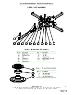
Page 19: ...06 19 10 20 30 SPIDER PLATE ASSEMBLY Figure 3 Greased Spider Plate Assembly Item Description Item Description 10 Spider Plate 70 Lift Lever 20 Grease Fitting 80 Jam Nut 30 Cap 90 Carriage Bolt 40 Tro...

Page 20: ...10822 10822 Caplug Grease Nipple Red 4 1 1 1997 40 10411A 10405A Trowel Arm 4 9 5 2000 50 10806 10806 HHCS 3 8 16 x 7 8 LG 4 1 1 1997 60 10805 10805 Lock Washer 3 8 Dia 4 1 1 1997 70 10817A 10819A Li...

Page 21: ...100 80 230 GEARBOX ASSEMBLY Figure 5 Gearbox Assembly Note B436 small gearbox shown Item Description Item Description Item Description Item Description 10 Gear Housing 80 Ball Bearing 150 End Cap 220...

Page 22: ...1 1 1 1997 90 10613 10613 Pressure Washer 2 1 1 1997 100 10601 10601 FHSCS 3 8 16 x 1 LG 8 1 1 1997 110 10621 10610 Oil Seal 1 1 16 ID x 1 5 8 OD x 5 16 THK EPDM 1 3 8 ID x 2 129 OD x 0 437 THK EPDM 1...

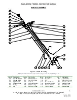
Page 23: ...list Item Description Item Description Item Description Item Description 10 Handle Bracket 70 Flat Hd Screw 125 Hex Nut 180 Lockwasher 20 Handle Clamp 80 Hex Hd Screw 130 Pin 190 Round Hd Screw 30 Ri...

Page 24: ...10538 10506 HHCS 3 8 16 x 2 1 4 LG 2 1 2 LG 1 1 1 1997 80 10507 10507 HHCS 3 8 16 x 1 LG 4 1 1 1997 90 10317 10317 Nylock Nut 3 8 16 6 1 1 1997 100 20302 20301 Hand Knob Assembly 1 1 1 1997 110 10314...

Page 25: ...Item Description Item Description 10 Handle Bracket 80 Hex Bolt 140 Socket Bolt 210 Deadman Wire 20 Handle Clamp 90 Locknut 150 Round Hd Screw 220 On Off Switch 30 Rigid Handle 100 Hand Lever Assy 16...

Page 26: ...80 10507 10507 HHCS 3 8 16 x 1 LG Gr5 4 1 1 1997 90 10317 10317 Nylock Nut 3 8 16 5 1 1 1997 100 14250 14250 Instapitch Adjust Lever 1 1 1 1997 110 14326 14326 Latch Disc Instapitch 1 2 07 06 120 1153...

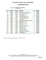
Page 27: ...TARIO CANADA L6S 5P6 905 458 5455 FAX 905 458 5484 590 HUEY RD SOUTH CAROLINA USA 29730 800 247 8577 FAX 800 633 5534 Created 07 04 Revised 4 06 27 30 20 40 10 BLADE KIT ASSEMBLY Figure 8 Finishing Bl...

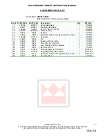
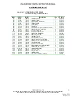
Page 28: ...247 8577 FAX 800 633 5534 Created 07 04 Revised 4 06 28 CUSTOMER PARTS LIST Assembly 20033 20068 FINISH BLADE KIT IMPERIAL Item Part 436 Part 446 Description Qty Eff Date 10 20414A 20480 Trowel Blade...

Page 29: ...T IDLE Idle too fast Belt too tight Clutch seized Pulley out of alignment TROWELS BLADES WEARING UNEVENLY Spider plate seized Arms bent Adjusting screws carriage bolts incorrectly set MACHINE JUMPS ON...

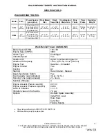
Page 30: ...es 3 Gal 12 5 L 2 hours Number of Blades 4 Engine Acoustic Power Lwa dB Engine Acoustic Pressure Lpa Db Level of Vibration Vibration value on the handle 97 103 82 86 1 1 1 5 7 0 aw Options Oil Bath Sp...

Page 31: ...Ltd Terex Light Construction 31 Sun Pac Blvd P O Box 3147 Brampton ON Canada Rock Hill SC L6S 5P6 U S A 29732 Tel 905 458 5455 Tel 1 800 247 8577 Fax 905 458 5484 Tel 1 800 324 3011 Overseas 905 458...

Page 32: ...INSTRUCTION MANUAL TEREX BARTELL LTD 31 SUN PAC BLVD BRAMPTON ONTARIO CANADA L6S 5P6 905 458 5455 FAX 905 458 5484 590 HUEY RD SOUTH CAROLINA USA 29730 800 247 8577 FAX 800 633 5534 Created 07 04 Rev...

Reviews: