background image

Important:  If  polarity  of  the  infrared  receiver  is  reversed,  receiver  and  Chromoflex  module  can  be
damaged!

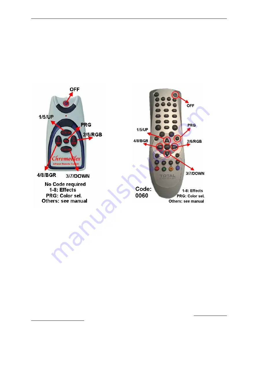
Infrared-Remote-Control - Operating

In  general  most  universal  remote  control  can  be  used,  whereas  only  6  keys  are  used.  The  small
„Zapper“ from OFA is a popular model and can be used without any further settings. Other models like
the „Promo 8“ require a setting as Philips device (for Promo 8 this is code 0060):

The 4 large buttons on the remote control are equivalent to the 4 „standard“ buttons (see first page,
(„+“ is button 1, „Right“ is button 2, „-’ is button 3, „Left“ is button 4).

Additionally the „Off“-button can be used to switch off all Chromoflex modules.

By pressing  the small button  in the middle  („PRG“ or  „Mute“), the programming  mode is entered.  At
first  all  modules  are  stopped,  so  the  current  colour  will  remain.  With  buttons  2  and  4  („Right“  and
„Left“) the active colour can be set (the active colour will blink while button 2 or 4 is pressed). Now the
active colour (as component) can be changed in 8 steps. The colour of the receiving module will be
transmitted to all other modules in the network, hence giving a homogenous colour for all modules.

The programming mode can only be left by pressing the „Off“-button!

Hint:  Try  to  set  up  the  colour  „white“:  White  consists  of  100%  green  and  about  30-50%  of  Red  and
Blue (depending on the used LEDs).

A Pool-Scenario

In this last paragraph we will describe a small „real world“ example:

Let’s assume you would like to illuminate a pool with several Chromoflex modules, but without using
any PC software or network:

The lamps are separated into 3 groups:

Chromoflex - Manual  - English V1.07 

- www.barthelme.de

Rev. 02.07.2006

- 10 -

Summary of Contents for CHROMOFLEX I350

Page 1: ...ng Chromoflex comes with several built in effects from calming colour change up to show effects External manual buttons DIP switches or a PC software can be used to control the modules Up to 30 module...

Page 2: ...rs marking obligation Particularly in connection with optics also weak LEDs can become very dangerous Staring into LEDs can cause irreparable damage to the eye s retina Hence NEVER STARE INTO THE BEAM...

Page 3: ...LEDs in series most high power LEDs for 350mA constant current require around 3 3 7 Volts depending on the colour type and manufacturerer Normally green and blue need the highest voltages the forward...

Page 4: ...all potentiometer on the supply where the output voltage can be adjusted within several percent We recommend to select the lowest voltage where all the LEDs work at full brightness without disturbance...

Page 5: ...e of the LED stripe Regarding any possible voltage drop please see the previous paragraph Cable lengths up to 5 Mtr are allowed Note We found LED stripes of 10 Volts 12 Volts and 24 Volts Note We also...

Page 6: ...perated in a network This means each module can either send or receive data For this the connectors RS232 RX ond RS232 GND are required The precondition for network operation is that all modules of th...

Page 7: ...s Colour transition time 10 seconds Effect 3 Randomly faded colours Blob Effect 4 User defined colour change can be changed by the Chromoflex Editor software for PC default is red green blue Effect 5...

Page 8: ...1 Standard colour change colour transition time 2 5 seconds default On Off Off Effect 2 Slow colour change colour transition time 10 seconds default Off On Off Effect 3 Randomly faded colours Blob On...

Page 9: ...tabele 1 Infrared Remote Control Installation For controlling one ore more modules connected as a network also the infrared control can be used Only one single module within a network should be equip...

Page 10: ...mode is entered At first all modules are stopped so the current colour will remain With buttons 2 and 4 Right and Left the active colour can be set the active colour will blink while button 2 or 4 is...

Page 11: ...n On On Ceiling That s really all to do Software 1 2 3 1 We offer the Chromoflex Editor for free download from our Internet site The software does contain additional documentation not covered by this...

Page 12: ...plies and has considerable advantages compared to traditional systems The modulation frequency is in the range from 120 Hz up to max 240 Hz Patent pending Maximum cable inductance can be calculated as...

Page 13: ...Attachment Module Pinout Chromoflex Manual English V1 07 www barthelme de Rev 02 07 2006 13...

Reviews: