background image

As first test the module will perform a standard colour change (this is the factory default). This effect
consists of 8 colours, each hold for 5 seconds, colour transition time is 2.5 seconds.

Diagnostic  LED:  The  modules  are  equipped  with  a  small  LED.  For  regular  operation  this  led  will
change all 2 seconds and it will flicker if data is transmitted (over the Bus).

Manual Buttons

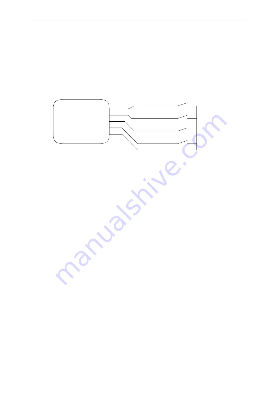
Each Chromoflex module is equipped with 4 inputs for buttons to select the effects:

Button 1

Button 2

Button 3

Button 4

SW-1
SW-2
SW-3
SW-4

SW-GND

ChromoFlex
Module

GND

Cable  length  for  the  buttons  may  be  up  to  10  Mtrs.  We  recommend  to  use  shielded  cables  for
distances over 1 Mtr, if operated in a (electrically) noisy environment. The shield should be connected
to SW-GND.

Remark: It is also possible to use remote controls or relay switches instead of manual buttons...

Networking

Many Chromoflex modules might be operated in a network. This means each module can either send
or receive data! For this the connectors RS232-RX ond RS232-GND are required.

The precondition for network operation is, that all modules of the network have a common GND of the
power supplies.

As  factory  default,  if  a  button  is  pressed  on  any  module,  it  will  pass  this  command  to  all  other
connected modules over the network.

Remark:  the  data  transmission  protocol  is  based  on  a  mathematical  algorithms,  that  is  very  robust
against transmission errors.

Important: For correct operation is required to add a resistor of around 10 kOhms (Low Cost) to the
bus. This resistor is included in the PC adapter kits, available from us. Shielded low frequency cable is
very well suited for the network lines. For short networks ( < 5 Mtrs.) Also unshielded cable is OK. The
10  kOhms  resistor  should  be  connected  between  RS232-RX  ond  RS232-GND  somewhere  in  the
network, from where also is the cable to the PC. The connection from module to module requires only
RS232-RX and the common GND.

Chromoflex - Manual  - English V1.07 

- www.barthelme.de

Rev. 02.07.2006

- 6 -

Summary of Contents for CHROMOFLEX I350

Page 1: ...ng Chromoflex comes with several built in effects from calming colour change up to show effects External manual buttons DIP switches or a PC software can be used to control the modules Up to 30 module...

Page 2: ...rs marking obligation Particularly in connection with optics also weak LEDs can become very dangerous Staring into LEDs can cause irreparable damage to the eye s retina Hence NEVER STARE INTO THE BEAM...

Page 3: ...LEDs in series most high power LEDs for 350mA constant current require around 3 3 7 Volts depending on the colour type and manufacturerer Normally green and blue need the highest voltages the forward...

Page 4: ...all potentiometer on the supply where the output voltage can be adjusted within several percent We recommend to select the lowest voltage where all the LEDs work at full brightness without disturbance...

Page 5: ...e of the LED stripe Regarding any possible voltage drop please see the previous paragraph Cable lengths up to 5 Mtr are allowed Note We found LED stripes of 10 Volts 12 Volts and 24 Volts Note We also...

Page 6: ...perated in a network This means each module can either send or receive data For this the connectors RS232 RX ond RS232 GND are required The precondition for network operation is that all modules of th...

Page 7: ...s Colour transition time 10 seconds Effect 3 Randomly faded colours Blob Effect 4 User defined colour change can be changed by the Chromoflex Editor software for PC default is red green blue Effect 5...

Page 8: ...1 Standard colour change colour transition time 2 5 seconds default On Off Off Effect 2 Slow colour change colour transition time 10 seconds default Off On Off Effect 3 Randomly faded colours Blob On...

Page 9: ...tabele 1 Infrared Remote Control Installation For controlling one ore more modules connected as a network also the infrared control can be used Only one single module within a network should be equip...

Page 10: ...mode is entered At first all modules are stopped so the current colour will remain With buttons 2 and 4 Right and Left the active colour can be set the active colour will blink while button 2 or 4 is...

Page 11: ...n On On Ceiling That s really all to do Software 1 2 3 1 We offer the Chromoflex Editor for free download from our Internet site The software does contain additional documentation not covered by this...

Page 12: ...plies and has considerable advantages compared to traditional systems The modulation frequency is in the range from 120 Hz up to max 240 Hz Patent pending Maximum cable inductance can be calculated as...

Page 13: ...Attachment Module Pinout Chromoflex Manual English V1 07 www barthelme de Rev 02 07 2006 13...

Reviews: