background image


Installation and operation 

16 / 28   


1043613 

EN 


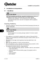
•  Connect the appliance to the gas supply 

connection with the DVGW approved 
connection hose, which features a 
cross-section suitable for the given 
rated power and length. 

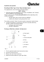
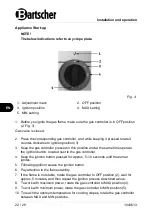
•  Gas connection (a) is located at the 

back of the appliance. 

Fig. 2 

 
•  Make sure that the gas connection hose does not run on or near hot surfaces, is 

not subject to stress or pressure and does not come into contact with sharp 
edges or other objects that could damage the hose. 

•  After connecting the appliance, all connection points between the installation 

and the appliance must be subject of tightness check. To this end, use spray for 
detecting leakages or foam producing agents, which do not spur corrosion. 
Connection points should be covered with an agent 

— no air bubbles should be 

produced. Also the gas shut-off valves should be subject of this check. 

NOTE! 

Do not use open fire to test tightness! 


Checking Gas Pressure and Rated Heat Load 

•  With first installation, the gas installation technician must check nominal heat 

load of the appliance, as we as perform maintenance.  

•  DO NOT attempt to increase the power nor rated heat load specified by the 

manufacturer.  

•  Check the rated heat pressure with gas meter and a stop watch. Measure 

exactly the amount of gas flowing per unit of time the appliance is consuming 
with maximum power.  

•  Compare the measured value with data on consumption in section 

'Technical 

Specifications'

, Table 3. Admissible deviation is ±5%.  


Summary of Contents for 1CP400G

Page 1: ...1CP400G 2CP400G 1043613 1043623...

Page 2: ...scher GmbH Franz Kleine Str 28 D 33154 Salzkotten Germany Phone 49 5258 971 0 Fax 49 5258 971 120 Service hotline 49 5258 971 197 www bartscher com 0705DM0001 Version 1 0 Date of preparation 2021 05 1...

Page 3: ...ght Protection 7 2 3 Declaration of Conformity 7 3 Transport Packaging and Storage 8 3 1 Delivery Check 8 3 2 Packaging 8 3 3 Storage 8 4 Technical Data 9 4 1 Technical Specifications 9 4 2 List of Co...

Page 4: ...s included in this manual is a prerequisite for safe and proper handling of the appliance Additionally accident prevention occupational health and safety and legal regulations in force in the area the...

Page 5: ...Safety instructions Safety of Gas Supplied Appliances Do not use a gas supplied appliance in the event of a malfunction or damage or in the case of a suspected malfunction or damage In such a case set...

Page 6: ...e near flammable or easily combustible materials e g petrol spirit alcohol High temperature triggers evaporation of these materials and as a result of contact with sources of ignition an explosion may...

Page 7: ...perated by qualified personnel and trained specialist personnel This appliance may not be operated by persons including children with limited physical sensory or mental capabilities nor by persons wit...

Page 8: ...ed standard use is prohibited and considered to be an unintended use The following is an intended use Cooking cr pes 1 4 Unintended Use An unintended use may lead to personal injuries or property dama...

Page 9: ...ntroduced by the user usage of unapproved spare parts We reserve the right to introduce technical modifications to the product intended for improvement of the appliance and its performance 2 2 Copyrig...

Page 10: ...used to store the appliance when relocating or when shipping the appliance to our service point in the case of any damages The packaging and its elements are made of recyclable materials Particularly...

Page 11: ...ronic ignition with battery ON OFF switch Gas cut off valve Control knob The set includes 1 AA battery Important Indication For use only in a well ventilated room or outdoors Gas connection set not in...

Page 12: ...cted load 6 kW Dimensions W x D x H in mm 860 x 545 x 225 Weight in kg 32 6 We reserve the right to implement technical modifications Gas Categories Destination Countries Gas categories Gas pressure m...

Page 13: ...ar 37 mbar 50 mbar Nozzle size small flame setting 0 7 mm fixed nozzle inside the gas valve Nozzle size 0 91 mm marked 0 91 0 85 mm marked 0 85 0 8 mm marked 0 8 Main burner type 1 5 mm x130 76 pcs 25...

Page 14: ...25 mbar 20 25 mbar Nozzle size small flame setting 0 7 mm fixed nozzle inside the gas valve Nozzle size 1 45 mm marked 1 45 Main burner type 1 5 mm x130 76 pcs 25 16 mm round SS304 burner T1 5 mm Mai...

Page 15: ...eet 4 pcs 5 Gas controller 6 Heat keeping tray 7 Igniter button Fig 1 4 3 Functions of the Appliance Supply with LPG makes the cr pe maker an appliance that may be used completely independently and ac...

Page 16: ...package materials for instance plastic bags and EPS If the appliance is covered with a protective film remove it Remove the film slowly so no glue residues are left Remove any glue residues with the...

Page 17: ...h per kW of appliance s rated power see appliance s rated plate Additionally accident prevention regulations should be observed Make sure that there are no objects near or under the appliance that may...

Page 18: ...se spray for detecting leakages or foam producing agents which do not spur corrosion Connection points should be covered with an agent no air bubbles should be produced Also the gas shut off valves sh...

Page 19: ...power the appliance nozzles and settings for each gas type that is used The number provided in Table 2 for proper nozzles is pressed on nozzles bodies 2 To adjust the appliance to the gas type with wh...

Page 20: ...e Functional Control Before test running install the appliance in a well ventilated room and remove any flammable materials from the vicinity of the appliance Before starting perform the tightness tes...

Page 21: ...service personnel The appliance should be used solely for cooking cr pes and should not be used for any other purpose The user is authorized to perform only everyday routine cleaning to maintain the a...

Page 22: ...t batter for approximately an hour with one of the controllers set to the setting between small and large flame Smoke may be produced This smoke is not harmful and will not be generated during subsequ...

Page 23: ...cr pe plates think cr pes are better for they are more subtle The batter slips on the cr pe plate or sticks to the spatula for spreading batter Do not grease Wipe the cr pe plate with a dry cloth A b...

Page 24: ...position and at the same time operate the ignition button located next to the gas controller 4 Keep the ignition button pressed for approx 5 10 seconds until the burner ignites 5 Following ignition r...

Page 25: ...with the spatula for spreading batter NOTE Pay attention to dosing the right amount of batter as otherwise the excess of batter will drip at sides 2 Meanwhile put the spatula for spreading batter into...

Page 26: ...isture oil nor fat do not enter the appliance Do not use water to clean hot plates Do not use any cleaning agents for cleaning of cr pe plates 1 Clean cr pe plates with a dry and paper towel or a damp...

Page 27: ...egularly When they are clogged clean burner arms with a hard hair brush 2 Do not use metal implements for cleaning injection nozzles They may modify technical properties of a burner 3 Also check regul...

Page 28: ...ng national and local regulations To this end we recommend contacting a professional company or local authorities unit proper for utilisation matters Before disposing of the appliance make sure that t...

Reviews: