background image

13

des  Geräts  angebracht  und  zugelassen  sein,  sowie  über  eine  der  Aufnahme  des  Geräts 
entsprechenden Stromfestigkeit verfügen (siehe technische Merkmale). 
Das  Gerät  muss  weiters  mit  einem  EQUIPOTENZIAL-Auschleich  verbunden  sein.  Die 
Klemmleiste  für  den  Anschluss  befindet  sich  nahe  der  Öffnung  für  das  Versorgungskabel  und  ist 
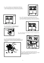
durch ein Etikett mit dem Symbol gekennzeichnet (Abb. 10 – S. 5). 
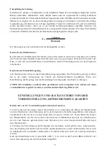
Wenn man eine Sicherheitsschalter benutzt, soll man den folgenden Anweisen folgen: 

-

Im Verhältnis zu dem Gericht, die verlorene Spannung für solche Maschine kann 1mA sein, 
ohne Begrenzung für dem Maximum für jede kW Leistung eingestellt. Außerdem muss man 
kontrollieren,  das  alle  Sicherheitsschalter,  die  im  Handel  sind,  eine  Toleranz  niedriger  als 
50% haben. Deshalb muss man einen richtigen Schalter wählen. 

-

Anschließen nur eine Maschine mit jedem Schalter. 

-

Nachdem  lange  Zeit  die  Maschine  nicht  gelaufen  hat  oder  im  Lager  gewesen  ist,  ist 
manchmal  möglich,  daß  bei  Inbetriebnahme  die  Sicherheitsschalter  eingeschaltet  werden. 
Die  wichtige  Ursache  ist  die  Isolierungsfeuchtigkeit.  Man  kann  das  Problem  einfach  lösen 
mit einer kurzen Heizung. Vorher muss man das Sicherheitsthermostat ausschalten. 

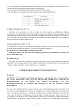
Anschluss an die Wasserversorgung 

Das  Wasserzuflussrohr  unter  Einhaltung  der  geltenden  gesetzlichen  Bestimmungen  mit  der 
Wasserversorgung verbinden.  

Anschluss an den Abfluss 

Das  Abflussrohr  darf  nicht  direkt  mit  der  gewöhnlichen  Abflussleitung  verbunden  werden,  sondern  muss 

oberhalb

  einer  Sammelgrube  positioniert  werden.  Der  Abstand  des  Rohrs  muss  so  groß  sein,  dass  jeder 

Kontakt  mit  den  Wänden  der  Sammelgrube  und  dem  in  ihr  enthaltenem  Wasser  vermieden  und  eine 
Verunreinigung der im Becken befindlichen Speisen verhindert wird.

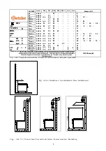
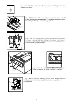
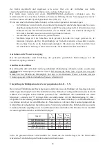
Überprüfung der Dichtigkeit und des Versorgungsdrucks (Abb. 11 – S. 5).  

Bevor mit der Überprüfung des Drucks begonnen werden kann, muss die Dichtigkeit der Gasanlage mit einem 
dafür vorgesehenen Spray bis zur Düse kontrolliert werden. Dadurch soll sichergestellt werden, dass das Gerät 
während  des  Transports  keinen  Schaden  genommen  hat.  Anschließend  den  Eintrittsdruck  mit  einem 
Manometer  -  entweder  aus  "U"-förmigen  Rohr  oder  elektronischer  Art  mit  Mindestzerlegung  0,1  mbar  - 
überprüfen. Um die Messung durchführen zu können, ist die Verschluss-Schraube (1) vom Druckanschluss (2) 
zu  entfernen  und  dieser  mit  dem  Röhrchen  des  Manometers  zu  verbinden.  Das  Gasversorgungsventil  des 
Geräts öffnen, den Abgabedruck überprüfen und das Ventil wieder schließen. Das Röhrchen entfernen und die 
Verschluss-Schraube sorgfältig wieder in den Druckanschluss einschrauben. Der Druckwert muss innerhalb 
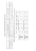
der unten angeführten Mindest- und Höchstwerte liegen: 

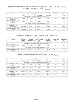
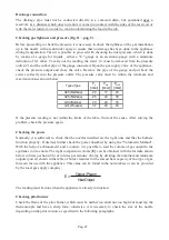
Sollte  der  gemessene  Druck  nicht  innerhalb  der  Grenzwerte  der  Tabelle  liegen,  ist  der  Grund  dafür 
festzustellen. Nach Behebung des Problems erneut den Druck messen. 

Gasart

P

[mbar]

P

min 

[mbar]

P

MAX 

[mbar]

G20 (Methangas)

20

17

25

G25 (Methangas)

20

17

25

G30 (Butangas)

50

42,5

57,5

G31 (Propangas)

50

42,5

57,5

Summary of Contents for 296.305

Page 1: ...TEIGWARENKOCHER PASTA COOKERS CUISEUR P TES CUOCIPASTA PASTAKOKERS GOTOWARKI MAKARONU SERIE 900 MASTER 296 305 295 3011 296 310 295 3051 D A CH GB UK F B CH I CH NL B PPL...

Page 2: ...er emptying Wasser entleeren Fig Abb 1 Dimensioni Dimensions Floor space dimensions Raumbedarfsmasse 2953051 G Gas Gaz C Carico acqua Remplissage d eau Water filling Wasser anf llen S Scarico acqua va...

Page 3: ...er emptying Wasser entleeren Fig Abb 3 Dimensioni Dimensions Floor space dimensions Raumbedarfsmasse 296305 E elettrico lectrique electric Elektrisch C Carico acqua Remplissage d eau Water filling Was...

Page 4: ...orberedt til brug af gas Za zen na plyn Toimib gaasi p hjal A berendez s g z haszn lat ra el k sz tett Sagatavota darbam ar g z Przysposobione na gas Numatyta dumjos Nastaven na plyn Pripravljeno za p...

Page 5: ...Abb 12 Sostituzione ugello bruciatore Regolazione dell aria primaria Changement du gicleur du br leur R glage de l air primaire Substituting the burner nozzle Regulating the primary air Austausch der...

Page 6: ...elkocher Fig Abb 18 Carico vasca Remplissage de la marmite Filling the tub Anf llen des Beckens Fig Abb 19 Scarico vasca Vidage de la marmite Emptying the tub Entleeren des Beckens Fig Abb 20 Sostituz...

Page 7: ...GASBETRIEBENE NUDELKOCHER ELEKTRISCHE NUDELKOCHER SERIE 900 MASTER INSTALLATION BENUTZUNG UND WARTUNG D A CH...

Page 8: ...00 x 2 280 x 2 125 x 2 51 x 2 3 0 Erdgase G25 13 80 x 2 3 00 x 2 310 x 2 125 x 2 51 x 2 3 0 Modell Beschreibung Ma e BxTxH mm Gas leist B Kw Typ A Verbrauch Fl ssiggas G30 D Kg h Verbrauch METHAN G20...

Page 9: ...Vorschriften und die Nichtbeachtung des vorliegenden Handbuchs zur ckzuf hren sind jegliche Verantwortung ab F r den Installateur Dem Benutzer muss der Betrieb des Ger ts erkl rt und vorgef hrt werde...

Page 10: ...ch den auf vier verschiedenen Positionen die Leistung von der Mindest bis zur H chststufe eingestellt werden kann Die Sicherheit des Ger ts wird durch ein von Hand r ckstellbaresSicherheitsthermostatg...

Page 11: ...abgase m ssen jedoch in daf r bestimmte Abzugshauben oder hnliche Vorrichtungen die mit einem leistungsf higen Kamin oder mit einer Abzugs ffnung direkt ins Freie verbunden sind abgeleitet werden Bei...

Page 12: ...r von der Voreinstellung abweichenden Gasart vorzugehen Der Anschluss an die am Boden des Ger ts vorhandene Gewindemuffe mit einem Durchmesser von Zoll kann unter Verwendung eines genormten Schnellans...

Page 13: ...arf nicht direkt mit der gew hnlichen Abflussleitung verbunden werden sondern muss oberhalb einer Sammelgrube positioniert werden Der Abstand des Rohrs muss so gro sein dass jeder Kontakt mit den W nd...

Page 14: ...Prim rluftregelung ausger stet Die berpr fung erfolgt an Hand der in der Spalte Luftregelung der Tabelle der Brennermerkmale angef hrten Werte Zur Durchf hrung der Regelung sind die Darstellungen der...

Page 15: ...ie Drehschalter wieder anbringen Austausch der Z ndbrennerd se Abb 15 S 5 F r den Austausch der Z ndbrennerd se ist die T r des Unterschranks zu ffnen der Anschluss 1 der die Leitung f r die Gasversor...

Page 16: ...dingt abzuschalten ACHTUNG Das Ger t nur unter Beaufsichtigung benutzen Den Nudelkocher niemals ohne Wasser in Betrieb setzen Betriebsst rungen Wenn sich das Ger t aus irgendeinem Grund nicht einschal...

Page 17: ...Stromkabels berpr fen Die Abzugsrohre der Ger te Typ B gem den im Aufstellungsland geltenden Vorschriften reinigen Der Gashahn sollte geschmiert werden da diese Arbeit jedoch m hsam und wenig sicher i...

Page 18: ...werden die Kabel nach dem Schaltplan wieder zusammengesteckt F R DEN AUSTAUSCH D RFEN AUSSCHLIESSLICH VOM HERSTELLER GELIEFERTE ORIGINALERSATZTEILE VERWENDET WERDEN DIE ARBEITEN M SSEN VON AUTORISIERT...

Page 19: ...GAS PASTA COOKERS ELECTRIC PASTA COOKERS SERIES 900 MASTER INSTALLATION USE AND MAINTENANCE GB UK...

Page 20: ...1 088 1 460 3 561 27 6 UNI ISO 7 1 R 300 UNI ISO 7 1 R 2953051 Gas pasta cooker 1 module 900x900x900 27 6 A1 B11 2 177 2 921 7 123 55 2 UNI ISO 7 1 R 300 UNI ISO 7 1 R 296310 Electric pasta cooker mod...

Page 21: ...tion x mm GAS PASTA COOKERS BURNER module Liquid gas LPG G30 G31 13 80 3 00 190 75 30 Open Natural Methane gas G20 13 80 3 00 280 125 51 3 0 Town gas G110 13 80 3 00 600 Reg 75 Open Town gas G120 13 8...

Page 22: ...kW Reduced capacity kW Diameter of main injectors 1 100 mm By Pass diameter 1 100 mm Pilot injectors N Air regulation x mm GAS PASTA COOKERS BURNER module Natural Methane gas G20 13 80 3 00 280 125 5...

Page 23: ...be handed over The user must be informed that any building modification or restructuring that may in any way modify the air supply necessary for combustion makes it necessary to carry out another chec...

Page 24: ...ating is done by means of elements protected with a sheath resistant to salted water PROVISIONS FOR INSTALLATION Place fig 6 pag 4 It is advisable to install the appliance in a well ventilated room or...

Page 25: ...ucts of combustion directly into external environment The energy supply to the appliance must be controlled by the system of forced evacuation and must be interrupted in the event that its capacity fa...

Page 26: ...panel of the top Furthermore the efficiency of the earth connection must be checked and also that the earth conductor on the connecting side is longer than the other conductors and that the connecting...

Page 27: ...ading is not within the limits of the table find out the cause After solving the problem check the pressure again Checking the power Normally it is sufficient to check that the nozzles installed are t...

Page 28: ...ner nozzle fig 12 pag 5 To substitute the burner nozzle it is necessary to open the door of the compartment After doing this the screw which blocks the regulation of primary air must be loosened 1 and...

Page 29: ...g that the heating elements are on It is advisable to regulate the element to the maximum temperature in order to reach the desired temperature right away and to leave it in this position for a few mi...

Page 30: ...ve synthetic sponge or stainless steel wool would be preferable to be used in the direction of the grain After washing dry with a soft cloth If the appliance is out of use for a long time it is advisa...

Page 31: ...Remove the protector 1 from the elements by loosening the fixing screws 2 unscrew the fixing screws 3 of the element to be substituted and after disconnecting remove it Electric components of the elec...

Page 32: ...MARMITES A GAZ MARMITES LECTRIQUES S RIE 900 MASTER INSTALLATION UTILISATION ET ENTRETIEN F B CH...

Page 33: ...R 300 UNI ISO 7 1 R 2953051 Marmite gaz 1 module 900x900x900 27 6 A1 B11 2 177 2 921 55 2 UNI ISO 7 1 R 300 UNI ISO 7 1 R 296310 Marmite lectrique module 450x900x900 10 230 3 400 3N 50 4x4 5 x 1 5 30...

Page 34: ...ons du fabricant figurant dans le manuel pr vu cet effet L utilisation de l appareil doit tre confi e des personnes qualifi es cet effet et en aucun cas l appareil ne doit tre utilis pour un usage aut...

Page 35: ...interne du panneau des commandes Les appareils ont t contr l s sur la base des directives europ ennes suivantes 2006 95 CE Basse tension LVD CEE 2004 108 Compatibilit lectromagn tique EMC 90 396 CEE A...

Page 36: ...en mat riau r fractaire permettant de maintenir la temp rature des parois dans les limites de s curit pr vues Installation Les op rations d installation les ventuelles interventions n cessaires l ali...

Page 37: ...ment coup e dans le cas o le d bit du syst me d vacuation deviendrait inf rieur aux valeurs pr vues par la norme applicable Le r tablissement de l alimentation de gaz ne doit tre possible que manuelle...

Page 38: ...ongueur sup rieure celle des autres conducteurs et de s assurer enfin que la section des conducteurs d alimentation est adapt e la puissance absorb e par l appareil elle doit tre au moins de type H05...

Page 39: ...ement Pour proc der un contr le proprement dit de la puissance il est possible d utiliser la m thode volum trique A l aide d un chronom tre et d un compteur il est possible de mesurer le volume de gaz...

Page 40: ...d un tournevis desserrer la vis de r glage de l air primaire 1 et placer en position d ouverture totale ce r glage 2 d visser ensuite le gicleur 3 l aide d une cl et le remplacer par le gicleur adapt...

Page 41: ...istances sur la temp rature maximum pour obtenir rapidement la temp rature voulue et de la laisser dans cette position pendant quelques minutes ensuite amener la commande dans la position correspondan...

Page 42: ...toutefois pr f rable d utiliser une ponge abrasive synth tique ou de la laine d acier inoxydable passer dans le sens du satinage Une fois le lavage termin essuyer l appareil l aide d un chiffon Dans l...

Page 43: ...les r sistances il est n cessaire d ouvrir le volet d acc s Retirer ensuite la protection des r sistances 1 en desserrant les vis de fixation 2 d visser les vis 3 de fixation de la r sistance changer...

Page 44: ...CUOCIPASTA A GAS CUOCIPASTA ELETTRICI SERIE 900 MASTER INSTALLAZIONE USO E MANUTENZIONE I CH...

Page 45: ...0 Cuocipasta elettrico modulo 450x900x900 10 230 3 400 3N 50 4x4 5 x 1 5 300 UNI ISO 7 1 R 296305 Cuocipasta elettrico 1 modulo 900x900x900 20 230 3 400 3N 50 4x10 5 x 4 300 UNI ISO 7 1 R Tabella 2 CA...

Page 46: ...i l inosservanza delle norme locali dall imperizia d uso e dalla non osservanza del presente libretto Per l installatore Deve essere spiegato e dimostrato all utente il funzionamento dell apparecchiat...

Page 47: ...gni vasca dotata di un commutatore che permette di variare la potenza dal massimo al minimo in quattro posizioni la sicurezza garantita da un termostato a riarmo manuale La vasca interamente costruita...

Page 48: ...zione forzata diretta fig 8 pag 4 Collegamento ad un camino a tiraggio forzato interponendo un interruttore di tiraggio con scarico dei prodotti della combustione direttamente in ambiente esterno L al...

Page 49: ...la corrispondenza tra le due si deve variare se previsto il cambio tensione il collegamento come illustrato nello schema elettrico Le morsettiere si trovano dietro il cruscotto Va verificata inoltre...

Page 50: ...limentazione dell apparecchiatura verificare la pressione in erogazione e richiudere la valvola Togliere il tubicino e riavvitare correttamente la vite nella presa di pressione Il valore della pressio...

Page 51: ...si trovano in una busta trasparente allegata al libretto di istruzioni Al termine della trasformazione verificare la tenuta dei raccordi e controllare che l accensione e il funzionamento del bruciator...

Page 52: ...posizione di accensione premere a fondo premere il pulsante del piezoelettrico 2 per accendere il bruciatore pilota mantenere premuta la manopola fino a quando la termocoppia si riscalda mantenendo il...

Page 53: ...ttazione del gas sia chiusa Durante le operazioni di pulizia dell apparecchio evitare di lavare utilizzando getti d acqua diretti o a pressione La pulizia deve essere fatta ad apparecchiatura fredda L...

Page 54: ...della conduttura che va al bruciatore il bocchettone della conduttura del bruciatore pilota la termocoppia ed infine il bocchettone della rampa Quindi sostituire il pezzo Termocoppia Per sostituire l...

Page 55: ...componenti dell impianto del gas si deve verificare la tenuta dello stesso ed il corretto funzionamento dei vari elementi IL COSTRUTTORE SI RISERVA IL DIRITTO DI MODIFICARE SENZA PREAVVISO LE CARATTER...

Page 56: ...GASPASTAKOKERS EN ELEKTRISCHE PASTAKOKERS SERIE 900 MASTER INSTALLATIE GEBRUIK EN ONDERHOUD NL B...

Page 57: ...57...

Page 58: ...58...

Page 59: ...59...

Page 60: ...60...

Page 61: ...61...

Page 62: ...raansluiting B A G30 G20 E m3 h V Hz mm2 kPa Kw D Kg h C m3 h Kw 2953011 Gaspastakoker module 450x900x900 13 8 A1 1 088 1 460 27 6 UNI ISO 7 1 R 300 UNI ISO 7 1 R 2953051 Gaspastakoker module 1 900x90...

Page 63: ...oeiers N Luchtregeling x mm GASBRANDER VOOR PASTAKOKERS module Vloeibaar gas LPG 13 80 3 00 190 75 30 Open G30 G31 Aardgas met een hoog methaangehalte 13 80 3 00 295 125 51 3 0 G25 GASBRANDER VOOR PAS...

Page 64: ...Et E E KW d s d E E WW E W h s D D 64...

Page 65: ...Z s E s E WW Z d E Z s Z s sKKZ Z E s E E d d s s t dZ d Z dZ d s...

Page 66: ...s t s Z sh Z s E d s s Z s s Z t E...

Page 67: ...E d d s s ZE ZK E...

Page 68: ...s Yh WKd Ed t h t s s h K K W W WD y E...

Page 69: ...E D K KW d sKKZ E E D d E KKZd t d s E Z E d E t K E s...

Page 70: ...s 60 K E W 60 E s 60 K E s 60 K s s Zh Et E K...

Page 71: ...s W d W t s K KW d s Z KZ E E KE Z Kh s E d WW Z d Z KW d s Z D D K E...

Page 72: ...K KW d s s D K s Zs E E s E KE Z E KW d s s K E d K s s K D...

Page 73: ...K s E h d h d E KZ E KE Z E s Z KKZ WZK h Ed DK E E E Z Zs KE Z E t Z D E DK d E tKZ E h d sK Z KKZ KKZ Z E s D E E KW d...

Page 74: ...GAZOWE I ELEKTRYCZNE GOTOWARKI MAKARONU SERIA 900 MASTER INSTALACJA U YTKOWANIE I KONSERWACJA PL...

Page 75: ...75...

Page 76: ...76...

Page 77: ...77...

Page 78: ...78...

Page 79: ...79...

Page 80: ...Maks ci nienie zasil Przy cze wodne 2953011 Gazowa gotowarka makaronu modu 450x 900x 900 13 8 A1 1 008 1 460 27 6 UNI I SO 7 1 R 300 UNI I SO 7 1 R 2953051 Gazowa gotowarka makaronu modu 1 900x 900x...

Page 81: ...Regulacja powietrza x mm PALNIK GAZOWY KUCHENEK DO MAKARONU modu u Gaz p ynny LPG 13 80 3 00 190 75 30 Otwarte G31 Gaz ziemny wysokometanowy 13 80 3 00 280 125 51 3 0 G20 PALNIK GAZOWY KUCHENEK DO MAK...

Page 82: ...t Mt W h h t E ht W h W h tB _ tK_ d E E W W d t t s D h Z...

Page 83: ...E KW hZ F K W K W WZ z KdKt E E d D h t W h s t dZ d Z dZ d Z W...

Page 84: ...s t D h t W t s t W sh E d t s W t W K W W E t K h h t t t t h W K W t W W...

Page 85: ...t t W E d W Z W t t W W W W t t W W W W E ZE MBdK KE K...

Page 86: ...D E K t W t W t W t d W W W W Z K W E K K t Z W W WD y W...

Page 87: ...t W W t t ht t h d t E tzD Ez t WZ zW h K D EE K ZK h h W t Z W W t D...

Page 88: ...t t W W Z W t W W W W W W t t W E dZh K Bh W W d...

Page 89: ...t t W W Z E E E K t W ht h W E KE Zt hZ E ht W W W E E d W...

Page 90: ...K ht W E tzD E _ ht W d d t E t E...

Page 91: ...t E W K _ D EE DK Bh z dz K KZz E E _ K d Z KE WZ WZK h Ed WZ WKt EEz z tz KEzt E WZ hdKZz Kt Ez W dMt ht W WZK h Ed dZ K WZ tK K D Ez tB _ tK_ WZ d t KEz dh WZK h dMt hWZ E...

Reviews: