background image

49

parti  esterne  della  macchina  con  acqua  tiepida  e  detersivo  utilizzando  uno  straccio  per  eliminare 
tutti  i  residui  rimasti  e  poi  asciugare  il  tutto  con  un  panno  morbido.  Se  ci  fossero  ancora  tracce 
residue  di  collante  rimuoverle  utilizzando  dei  solventi  adatti  (es.  acetone).  Per  nessun  motivo 
utilizzare  sostanze  abrasive.  L’apparecchiatura  dopo  essere  stata  posta  in  opera,  dovrà  essere 
livellata utilizzando la regolazione permessa dai piedini. 

Allacciamento Gas 

Prima  di  allacciare  l’apparecchiatura  si  deve  verificare  la  corrispondenza  tra  il  gas  di 

predisposizione della stessa e quello disponibile per l’alimentazione, al fine di verificarne l’idoneità. 
Se  non  si  trova  la  corrispondenza  tra  i  due  si  deve  procedere  come  descritto  nel  paragrafo 

“Funzionamento  con  gas  diverso  dalla  predisposizione”

.  L’allacciamento  al  manicotto  filettato 

avente un diametro di ¾ di pollice, presente sul fondo dell’apparecchio, può essere fisso o mobile 
utilizzando un raccordo rapido a norma. Se si usano delle condutture flessibili, queste devono essere 
in acciaio inossidabile e rispondenti alla norma. Tutte le tenute sui filetti di giunzione devono essere 
garantite  da  materiali  certificati  per  l’utilizzo  con  i  gas.  A  monte  di  ogni  singola  apparecchiatura 
deve  essere  installato  un  rubinetto  di  intercettazione,  posto  in  posizione  facilmente  accessibile  in 
modo  tale  da  permettere  di  chiudere  il  gas  a  fine  lavoro.  Completato  l’allacciamento,  si  deve 
verificare la tenuta di quest’ultimo con l’ausilio dell’apposito spray rilevatore di fughe. 

Allacciamento Elettrico 

Prima  di  allacciare  l’apparecchiatura  si  deve  verificare  la  corrispondenza  tra  la  tensione  di 
predisposizione della stessa e quella disponibile per l’alimentazione al fine di verificarne l’idoneità. 
Se  non  si  trova  la  corrispondenza  tra  le  due  si  deve  variare,  se  previsto  il  cambio  tensione,  il 
collegamento,  come  illustrato  nello  schema  elettrico.  Le  morsettiere  si  trovano  dietro  il  cruscotto. 
Va verificata inoltre l’efficacia della messa a terra, che il conduttore di terra dal lato allacciamento 
sia  più  lungo  degli  altri  conduttori,  che  il  cavo  d’allacciamento  abbia  una  sezione  adeguato  alla 
potenza assorbita dall’apparecchiatura e che sia almeno di tipo H05 RN-F. 

Come da disposizioni 

internazionali,  a  monte  dell’apparecchiatura  stessa  deve  essere  installato  un  dispositivo 
onnipolare  con  un’apertura  dei  contatti  di  almeno  3  mm,  che  non deve  interrompere  il  cavo 
GIALLO-VERDE  di  terra

.  Il dispositivo deve essere installato nelle vicinanze dell’apparecchio, 

deve  essere  omologato  ed  avere  una  portata  adatta  all’assorbimento  dell’apparecchiatura  (Vedi 
caratteristiche tecniche). 
L’apparecchiatura  deve  essere  collegata  al  sistema  EQUIPOTENZIALE.  Il  morsetto  per  il 
collegamento  è  situato  vicino  all’entrata  del  cavo  di  alimentazione  ed  è  contraddistinto  da 
un’etichetta (fig.10 – pag.5). 
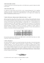
Con l’utilizzo di un interruttore di sicurezza per correnti di guasto bisogna osservare quanto segue:  

-

Secondo la normativa vigente, la corrente dispersa per apparecchiature di questo genere può 
avere il valore di 1mA senza limitazione del massimo per ogni kW di potenza installata. Si 
dovrà inoltre osservare che tutti gli interruttori per correnti di guasto reperibili sul mercato 
abbiano una tolleranza per la corrente di scatto di meno 50% e quindi dovrà essere scelto un 
interruttore idoneo. 

-

Collegare solo un apparecchio per ogni interruttore 

-

In alcuni casi è possibile che l’apparecchio dopo periodi prolungati di fermo a magazzino, di 
inattività  o  in  caso  di  nuova  installazione,  faccia  scattare  l’interruttore  durante  la  messa  in 
funzione. La causa è da ricondursi per lo più all’umidità di isolamento. Il problema si risolve 
con un breve riscaldamento a secco by-passando l’interruttore di sicurezza. 

Summary of Contents for 296.305

Page 1: ...TEIGWARENKOCHER PASTA COOKERS CUISEUR P TES CUOCIPASTA PASTAKOKERS GOTOWARKI MAKARONU SERIE 900 MASTER 296 305 295 3011 296 310 295 3051 D A CH GB UK F B CH I CH NL B PPL...

Page 2: ...er emptying Wasser entleeren Fig Abb 1 Dimensioni Dimensions Floor space dimensions Raumbedarfsmasse 2953051 G Gas Gaz C Carico acqua Remplissage d eau Water filling Wasser anf llen S Scarico acqua va...

Page 3: ...er emptying Wasser entleeren Fig Abb 3 Dimensioni Dimensions Floor space dimensions Raumbedarfsmasse 296305 E elettrico lectrique electric Elektrisch C Carico acqua Remplissage d eau Water filling Was...

Page 4: ...orberedt til brug af gas Za zen na plyn Toimib gaasi p hjal A berendez s g z haszn lat ra el k sz tett Sagatavota darbam ar g z Przysposobione na gas Numatyta dumjos Nastaven na plyn Pripravljeno za p...

Page 5: ...Abb 12 Sostituzione ugello bruciatore Regolazione dell aria primaria Changement du gicleur du br leur R glage de l air primaire Substituting the burner nozzle Regulating the primary air Austausch der...

Page 6: ...elkocher Fig Abb 18 Carico vasca Remplissage de la marmite Filling the tub Anf llen des Beckens Fig Abb 19 Scarico vasca Vidage de la marmite Emptying the tub Entleeren des Beckens Fig Abb 20 Sostituz...

Page 7: ...GASBETRIEBENE NUDELKOCHER ELEKTRISCHE NUDELKOCHER SERIE 900 MASTER INSTALLATION BENUTZUNG UND WARTUNG D A CH...

Page 8: ...00 x 2 280 x 2 125 x 2 51 x 2 3 0 Erdgase G25 13 80 x 2 3 00 x 2 310 x 2 125 x 2 51 x 2 3 0 Modell Beschreibung Ma e BxTxH mm Gas leist B Kw Typ A Verbrauch Fl ssiggas G30 D Kg h Verbrauch METHAN G20...

Page 9: ...Vorschriften und die Nichtbeachtung des vorliegenden Handbuchs zur ckzuf hren sind jegliche Verantwortung ab F r den Installateur Dem Benutzer muss der Betrieb des Ger ts erkl rt und vorgef hrt werde...

Page 10: ...ch den auf vier verschiedenen Positionen die Leistung von der Mindest bis zur H chststufe eingestellt werden kann Die Sicherheit des Ger ts wird durch ein von Hand r ckstellbaresSicherheitsthermostatg...

Page 11: ...abgase m ssen jedoch in daf r bestimmte Abzugshauben oder hnliche Vorrichtungen die mit einem leistungsf higen Kamin oder mit einer Abzugs ffnung direkt ins Freie verbunden sind abgeleitet werden Bei...

Page 12: ...r von der Voreinstellung abweichenden Gasart vorzugehen Der Anschluss an die am Boden des Ger ts vorhandene Gewindemuffe mit einem Durchmesser von Zoll kann unter Verwendung eines genormten Schnellans...

Page 13: ...arf nicht direkt mit der gew hnlichen Abflussleitung verbunden werden sondern muss oberhalb einer Sammelgrube positioniert werden Der Abstand des Rohrs muss so gro sein dass jeder Kontakt mit den W nd...

Page 14: ...Prim rluftregelung ausger stet Die berpr fung erfolgt an Hand der in der Spalte Luftregelung der Tabelle der Brennermerkmale angef hrten Werte Zur Durchf hrung der Regelung sind die Darstellungen der...

Page 15: ...ie Drehschalter wieder anbringen Austausch der Z ndbrennerd se Abb 15 S 5 F r den Austausch der Z ndbrennerd se ist die T r des Unterschranks zu ffnen der Anschluss 1 der die Leitung f r die Gasversor...

Page 16: ...dingt abzuschalten ACHTUNG Das Ger t nur unter Beaufsichtigung benutzen Den Nudelkocher niemals ohne Wasser in Betrieb setzen Betriebsst rungen Wenn sich das Ger t aus irgendeinem Grund nicht einschal...

Page 17: ...Stromkabels berpr fen Die Abzugsrohre der Ger te Typ B gem den im Aufstellungsland geltenden Vorschriften reinigen Der Gashahn sollte geschmiert werden da diese Arbeit jedoch m hsam und wenig sicher i...

Page 18: ...werden die Kabel nach dem Schaltplan wieder zusammengesteckt F R DEN AUSTAUSCH D RFEN AUSSCHLIESSLICH VOM HERSTELLER GELIEFERTE ORIGINALERSATZTEILE VERWENDET WERDEN DIE ARBEITEN M SSEN VON AUTORISIERT...

Page 19: ...GAS PASTA COOKERS ELECTRIC PASTA COOKERS SERIES 900 MASTER INSTALLATION USE AND MAINTENANCE GB UK...

Page 20: ...1 088 1 460 3 561 27 6 UNI ISO 7 1 R 300 UNI ISO 7 1 R 2953051 Gas pasta cooker 1 module 900x900x900 27 6 A1 B11 2 177 2 921 7 123 55 2 UNI ISO 7 1 R 300 UNI ISO 7 1 R 296310 Electric pasta cooker mod...

Page 21: ...tion x mm GAS PASTA COOKERS BURNER module Liquid gas LPG G30 G31 13 80 3 00 190 75 30 Open Natural Methane gas G20 13 80 3 00 280 125 51 3 0 Town gas G110 13 80 3 00 600 Reg 75 Open Town gas G120 13 8...

Page 22: ...kW Reduced capacity kW Diameter of main injectors 1 100 mm By Pass diameter 1 100 mm Pilot injectors N Air regulation x mm GAS PASTA COOKERS BURNER module Natural Methane gas G20 13 80 3 00 280 125 5...

Page 23: ...be handed over The user must be informed that any building modification or restructuring that may in any way modify the air supply necessary for combustion makes it necessary to carry out another chec...

Page 24: ...ating is done by means of elements protected with a sheath resistant to salted water PROVISIONS FOR INSTALLATION Place fig 6 pag 4 It is advisable to install the appliance in a well ventilated room or...

Page 25: ...ucts of combustion directly into external environment The energy supply to the appliance must be controlled by the system of forced evacuation and must be interrupted in the event that its capacity fa...

Page 26: ...panel of the top Furthermore the efficiency of the earth connection must be checked and also that the earth conductor on the connecting side is longer than the other conductors and that the connecting...

Page 27: ...ading is not within the limits of the table find out the cause After solving the problem check the pressure again Checking the power Normally it is sufficient to check that the nozzles installed are t...

Page 28: ...ner nozzle fig 12 pag 5 To substitute the burner nozzle it is necessary to open the door of the compartment After doing this the screw which blocks the regulation of primary air must be loosened 1 and...

Page 29: ...g that the heating elements are on It is advisable to regulate the element to the maximum temperature in order to reach the desired temperature right away and to leave it in this position for a few mi...

Page 30: ...ve synthetic sponge or stainless steel wool would be preferable to be used in the direction of the grain After washing dry with a soft cloth If the appliance is out of use for a long time it is advisa...

Page 31: ...Remove the protector 1 from the elements by loosening the fixing screws 2 unscrew the fixing screws 3 of the element to be substituted and after disconnecting remove it Electric components of the elec...

Page 32: ...MARMITES A GAZ MARMITES LECTRIQUES S RIE 900 MASTER INSTALLATION UTILISATION ET ENTRETIEN F B CH...

Page 33: ...R 300 UNI ISO 7 1 R 2953051 Marmite gaz 1 module 900x900x900 27 6 A1 B11 2 177 2 921 55 2 UNI ISO 7 1 R 300 UNI ISO 7 1 R 296310 Marmite lectrique module 450x900x900 10 230 3 400 3N 50 4x4 5 x 1 5 30...

Page 34: ...ons du fabricant figurant dans le manuel pr vu cet effet L utilisation de l appareil doit tre confi e des personnes qualifi es cet effet et en aucun cas l appareil ne doit tre utilis pour un usage aut...

Page 35: ...interne du panneau des commandes Les appareils ont t contr l s sur la base des directives europ ennes suivantes 2006 95 CE Basse tension LVD CEE 2004 108 Compatibilit lectromagn tique EMC 90 396 CEE A...

Page 36: ...en mat riau r fractaire permettant de maintenir la temp rature des parois dans les limites de s curit pr vues Installation Les op rations d installation les ventuelles interventions n cessaires l ali...

Page 37: ...ment coup e dans le cas o le d bit du syst me d vacuation deviendrait inf rieur aux valeurs pr vues par la norme applicable Le r tablissement de l alimentation de gaz ne doit tre possible que manuelle...

Page 38: ...ongueur sup rieure celle des autres conducteurs et de s assurer enfin que la section des conducteurs d alimentation est adapt e la puissance absorb e par l appareil elle doit tre au moins de type H05...

Page 39: ...ement Pour proc der un contr le proprement dit de la puissance il est possible d utiliser la m thode volum trique A l aide d un chronom tre et d un compteur il est possible de mesurer le volume de gaz...

Page 40: ...d un tournevis desserrer la vis de r glage de l air primaire 1 et placer en position d ouverture totale ce r glage 2 d visser ensuite le gicleur 3 l aide d une cl et le remplacer par le gicleur adapt...

Page 41: ...istances sur la temp rature maximum pour obtenir rapidement la temp rature voulue et de la laisser dans cette position pendant quelques minutes ensuite amener la commande dans la position correspondan...

Page 42: ...toutefois pr f rable d utiliser une ponge abrasive synth tique ou de la laine d acier inoxydable passer dans le sens du satinage Une fois le lavage termin essuyer l appareil l aide d un chiffon Dans l...

Page 43: ...les r sistances il est n cessaire d ouvrir le volet d acc s Retirer ensuite la protection des r sistances 1 en desserrant les vis de fixation 2 d visser les vis 3 de fixation de la r sistance changer...

Page 44: ...CUOCIPASTA A GAS CUOCIPASTA ELETTRICI SERIE 900 MASTER INSTALLAZIONE USO E MANUTENZIONE I CH...

Page 45: ...0 Cuocipasta elettrico modulo 450x900x900 10 230 3 400 3N 50 4x4 5 x 1 5 300 UNI ISO 7 1 R 296305 Cuocipasta elettrico 1 modulo 900x900x900 20 230 3 400 3N 50 4x10 5 x 4 300 UNI ISO 7 1 R Tabella 2 CA...

Page 46: ...i l inosservanza delle norme locali dall imperizia d uso e dalla non osservanza del presente libretto Per l installatore Deve essere spiegato e dimostrato all utente il funzionamento dell apparecchiat...

Page 47: ...gni vasca dotata di un commutatore che permette di variare la potenza dal massimo al minimo in quattro posizioni la sicurezza garantita da un termostato a riarmo manuale La vasca interamente costruita...

Page 48: ...zione forzata diretta fig 8 pag 4 Collegamento ad un camino a tiraggio forzato interponendo un interruttore di tiraggio con scarico dei prodotti della combustione direttamente in ambiente esterno L al...

Page 49: ...la corrispondenza tra le due si deve variare se previsto il cambio tensione il collegamento come illustrato nello schema elettrico Le morsettiere si trovano dietro il cruscotto Va verificata inoltre...

Page 50: ...limentazione dell apparecchiatura verificare la pressione in erogazione e richiudere la valvola Togliere il tubicino e riavvitare correttamente la vite nella presa di pressione Il valore della pressio...

Page 51: ...si trovano in una busta trasparente allegata al libretto di istruzioni Al termine della trasformazione verificare la tenuta dei raccordi e controllare che l accensione e il funzionamento del bruciator...

Page 52: ...posizione di accensione premere a fondo premere il pulsante del piezoelettrico 2 per accendere il bruciatore pilota mantenere premuta la manopola fino a quando la termocoppia si riscalda mantenendo il...

Page 53: ...ttazione del gas sia chiusa Durante le operazioni di pulizia dell apparecchio evitare di lavare utilizzando getti d acqua diretti o a pressione La pulizia deve essere fatta ad apparecchiatura fredda L...

Page 54: ...della conduttura che va al bruciatore il bocchettone della conduttura del bruciatore pilota la termocoppia ed infine il bocchettone della rampa Quindi sostituire il pezzo Termocoppia Per sostituire l...

Page 55: ...componenti dell impianto del gas si deve verificare la tenuta dello stesso ed il corretto funzionamento dei vari elementi IL COSTRUTTORE SI RISERVA IL DIRITTO DI MODIFICARE SENZA PREAVVISO LE CARATTER...

Page 56: ...GASPASTAKOKERS EN ELEKTRISCHE PASTAKOKERS SERIE 900 MASTER INSTALLATIE GEBRUIK EN ONDERHOUD NL B...

Page 57: ...57...

Page 58: ...58...

Page 59: ...59...

Page 60: ...60...

Page 61: ...61...

Page 62: ...raansluiting B A G30 G20 E m3 h V Hz mm2 kPa Kw D Kg h C m3 h Kw 2953011 Gaspastakoker module 450x900x900 13 8 A1 1 088 1 460 27 6 UNI ISO 7 1 R 300 UNI ISO 7 1 R 2953051 Gaspastakoker module 1 900x90...

Page 63: ...oeiers N Luchtregeling x mm GASBRANDER VOOR PASTAKOKERS module Vloeibaar gas LPG 13 80 3 00 190 75 30 Open G30 G31 Aardgas met een hoog methaangehalte 13 80 3 00 295 125 51 3 0 G25 GASBRANDER VOOR PAS...

Page 64: ...Et E E KW d s d E E WW E W h s D D 64...

Page 65: ...Z s E s E WW Z d E Z s Z s sKKZ Z E s E E d d s s t dZ d Z dZ d s...

Page 66: ...s t s Z sh Z s E d s s Z s s Z t E...

Page 67: ...E d d s s ZE ZK E...

Page 68: ...s Yh WKd Ed t h t s s h K K W W WD y E...

Page 69: ...E D K KW d sKKZ E E D d E KKZd t d s E Z E d E t K E s...

Page 70: ...s 60 K E W 60 E s 60 K E s 60 K s s Zh Et E K...

Page 71: ...s W d W t s K KW d s Z KZ E E KE Z Kh s E d WW Z d Z KW d s Z D D K E...

Page 72: ...K KW d s s D K s Zs E E s E KE Z E KW d s s K E d K s s K D...

Page 73: ...K s E h d h d E KZ E KE Z E s Z KKZ WZK h Ed DK E E E Z Zs KE Z E t Z D E DK d E tKZ E h d sK Z KKZ KKZ Z E s D E E KW d...

Page 74: ...GAZOWE I ELEKTRYCZNE GOTOWARKI MAKARONU SERIA 900 MASTER INSTALACJA U YTKOWANIE I KONSERWACJA PL...

Page 75: ...75...

Page 76: ...76...

Page 77: ...77...

Page 78: ...78...

Page 79: ...79...

Page 80: ...Maks ci nienie zasil Przy cze wodne 2953011 Gazowa gotowarka makaronu modu 450x 900x 900 13 8 A1 1 008 1 460 27 6 UNI I SO 7 1 R 300 UNI I SO 7 1 R 2953051 Gazowa gotowarka makaronu modu 1 900x 900x...

Page 81: ...Regulacja powietrza x mm PALNIK GAZOWY KUCHENEK DO MAKARONU modu u Gaz p ynny LPG 13 80 3 00 190 75 30 Otwarte G31 Gaz ziemny wysokometanowy 13 80 3 00 280 125 51 3 0 G20 PALNIK GAZOWY KUCHENEK DO MAK...

Page 82: ...t Mt W h h t E ht W h W h tB _ tK_ d E E W W d t t s D h Z...

Page 83: ...E KW hZ F K W K W WZ z KdKt E E d D h t W h s t dZ d Z dZ d Z W...

Page 84: ...s t D h t W t s t W sh E d t s W t W K W W E t K h h t t t t h W K W t W W...

Page 85: ...t t W E d W Z W t t W W W W t t W W W W E ZE MBdK KE K...

Page 86: ...D E K t W t W t W t d W W W W Z K W E K K t Z W W WD y W...

Page 87: ...t W W t t ht t h d t E tzD Ez t WZ zW h K D EE K ZK h h W t Z W W t D...

Page 88: ...t t W W Z W t W W W W W W t t W E dZh K Bh W W d...

Page 89: ...t t W W Z E E E K t W ht h W E KE Zt hZ E ht W W W E E d W...

Page 90: ...K ht W E tzD E _ ht W d d t E t E...

Page 91: ...t E W K _ D EE DK Bh z dz K KZz E E _ K d Z KE WZ WZK h Ed WZ WKt EEz z tz KEzt E WZ hdKZz Kt Ez W dMt ht W WZK h Ed dZ K WZ tK K D Ez tB _ tK_ WZ d t KEz dh WZK h dMt hWZ E...

Reviews: