background image

Installation and operation  


105862   


17 / 40 

EN 


Connection 

— Electrical Power 

•  Verify if the technical specification of the appliance (see the rating plate) 

correspond to the local electricity grid. 

•  Electrical connection of the appliance to mains power supply must be executed 

by a qualified electrician, according to international, national and local 
regulations in force. 

•  The induction cooker is equipped with power cord. It must be connected with a 

plug or directly into a suitable mains wall socket. 


•  When connecting the appliance to electric power supply, do not use adapters, 

reducers nor multiple sockets. 

•  The power cord may not come in contact with any of hot elements and must be 

routed so that it is not subject to influence of temperature exceeding 75°C. 


•  Do not use the appliance with an external timer or remote control. 


5.2


Operation 


Method of operation of heating plates 

In induction cookers the electric voltage is applied to a conductive coil under the 
glass. This generates magnetic field, which being a physical effect, heats the 
bottom of a cookware directly. 

This translates to savings of time and energy, as 

— contradictory to traditional 

heating areas 

— there is no heating up of a heater and then of the glass heating 

plate.  

Another advantage of the technical features described above is the very short 
cooking time. 

Additionally, inflow of heat changes instantly with every change of settings and it 
may be controlled precisely. The induction heating plate reacts to changes in 
settings as fast a gas cooker, for the energy is delivered immediately to a pot, 
without the need to prior heating up of other materials.   

The induction technology combines the speed of reaction with a basic benefit of the 
current, making it possible to precisely control heat inflow.  


Summary of Contents for IKF 72-2Z

Page 1: ...IKF 72 2Z 105862...

Page 2: ...scher GmbH Franz Kleine Str 28 D 33154 Salzkotten Germany Phone 49 5258 971 0 Fax 49 5258 971 120 Technical Support Hotline 49 5258 971 197 www bartscher com Version 1 0 Date of preparation 2020 09 08...

Page 3: ...tion of Conformity 8 3 Transport Packaging and Storage 9 3 1 Delivery Check 9 3 2 Packaging 9 3 3 Storage 9 4 Technical Data 10 4 1 Technical Specifications 10 4 2 List of Components of the Appliance...

Page 4: ...included in this manual is a prerequisite for safe and proper handling of the appliance Additionally accident prevention occupational health and safety and legal regulations in force in the area the...

Page 5: ...nt Too high a mains voltage or incorrect installation may cause electric shock The appliance may be connected only if data on the rating plate correspond with the mains voltage To avoid short circuit...

Page 6: ...tc High temperature triggers evaporation of these materials and as a result of contact with sources of ignition an explosion may occur In case of fire disconnect the appliance from the power supply be...

Page 7: ...f damage even if it is only a small fracture the device should be immediately disconnected from the power supply and you should contact the service company Electromagnetic Fields Magnetized items e g...

Page 8: ...e and possible risks Children should not play with the device Do not leave the device unattended in the presence of children Cleaning and user maintenance may not be performed by children Children tha...

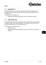
Page 9: ...tended use Preparing and heating up foods with the use of suitable cookware 1 4 Unintended Use An unintended use may lead to personal injuries or property damages caused by hazardous voltage fire or h...

Page 10: ...troduced by the user usage of unapproved spare parts We reserve the right to introduce technical modifications to the product intended for improvement of the appliance and its performance 2 2 Copyrigh...

Page 11: ...used to store the appliance when relocating or when shipping the appliance to our service point in the case of any damages The packaging and its elements are made of recyclable materials Particularly...

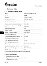
Page 12: ...ut of hobs 1 8 kW 3 kW Output of induction zones 3 kW 4 kW Number of output levels 9 Temperature range min max in C 0 99 5 Number of temperature levels 9 Time setting from to in min 1 99 Time setting...

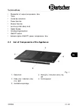
Page 13: ...Booster function Lock key child safety lock Digital display Overheating protection ON OFF switch Indicator lights ON OFF power temperature time 4 2 List of Components of the Appliance Fig 1 1 Glass h...

Page 14: ...and in compliance with the applicable national law NOTE The manufacturer disclaims all liability and provides no warranty for damages which may be attributed to non observance of regulations or incorr...

Page 15: ...erator freezer washing machine or clotheshorse as humidity may damage electronics of the heating plate an oven features a built in fan should the appliance be installed over an oven the installation m...

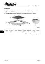
Page 16: ...he opening in the worktop table board according to data provide in the figure and table below 2 During installation leave at least 50 mm clearance around the opening Fig 2 L mm W mm H mm D mm A mm B m...

Page 17: ...mm Table 2 3 Make sure that the induction plate is well ventilated and the air inlet and air outlet are not obstructed WARNING Accidental touching of the overheated base of the induction plate during...

Page 18: ...n installing the heating plate make sure they are not obstructed by the worktop table Remember that the adhesive binding plastics or wood with furniture must withstand the temperatures of over 150 C t...

Page 19: ...h an external timer or remote control 5 2 Operation Method of operation of heating plates In induction cookers the electric voltage is applied to a conductive coil under the glass This generates magne...

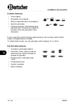
Page 20: ...he description of the cookware Due to a specific way the induction plate operates only cookware with a bottom subject to magnetization is suitable To obtain better results use only pans pots with a di...

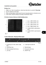
Page 21: ...gs according to indications below Division of power between hobs heating zones 1 max 1 800 3 000 W hob 2 max 1 800 3 000 W hob 3 max 1 800 3 000 W hob 4 max 1 800 3 000 W hob 5 3 000 4 000 W left indu...

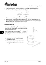
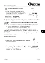
Page 22: ...ith any objects e g kitchenware or cloths Even a thin layer of water film may hinder the operation of control elements Appliance Start Up 1 Touch the ON OFF key in the control panel After switching on...

Page 23: ...ing the cooking process If and the cooking level blink interchangeably in the display it means that no cookware was placed on the suitable heating zone the used cookware is not suitable for induction...

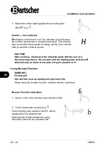
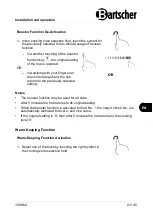
Page 24: ...duction plate with the use of a disconnecting device Do not wait until the heating plate switches off automatically as there are no pots not pans present on it Using Booster Function WARNING Fire haza...

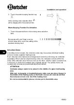
Page 25: ...ol range field the hob returns to the previously selected setting Notes The booster function may be used for all hobs After 5 minutes the hob returns to its original setting When the booster function...

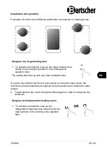
Page 26: ...one features two independent inductors which may be controlled separately When used as single heating zones the cookware is move within the limits of the induction zone from one zone to the other with...

Page 27: ...ld The setting functions as with any other standard zone If a pot is moved from the front to rear section or the other way round the induction zone automatically recognises the new position and retain...

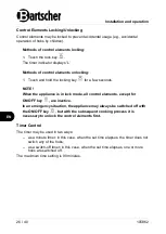
Page 28: ...NOTE When the appliance is in lock mode all control elements except for ON OFF key are inactive In an emergency situation the appliance may always be switched off with the ON OFF key but with the sub...

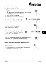
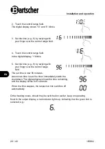
Page 29: ...6 by swiping with your finger over the control range field 4 Touch the control range field In the digital display 1 blinks 5 Set the time e g 9 by swiping with your finger over the control range fiel...

Page 30: ...9 by swiping with your finger over the control range field The set time is now 96 minutes As soon as time is set the timer immediately starts the countdown The digital display shows the time remaining...

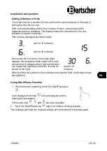
Page 31: ...time set in the minute timer elapses the respective hobs switch off A new minute timer is displayed then and red indicator of a respective heating zone blinks It looks as shown to the right set for 3...

Page 32: ...ting and then reduced when the prepared food is heated up or boiling Using lids shortens the cooking time and saves energy as heat is arrested When cooking with lid on decrease the cooking level as so...

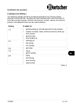
Page 33: ...g prepared With the trial and error method operate the induction plate to find settings that best suit the selected dishes Setting Suitable for 1 2 gentle heating up of small amounts of food products...

Page 34: ...austic abrasive cleaning agents may scratch glass Use only suitable cleaning agents or special sponges for ceramic glass of induction plates Observe the instructions of manufacturers of cleaning and a...

Page 35: ...hazard The blade of the glass scrapper is very sharp when the protective cover is removed Exercise caution when using glass scrapper Glass scrapper should be kept away from the reach of children 8 St...

Page 36: ...d Unlock the touch control observe indications in Control Elements Locking Unlocking section Touch control is difficult to operate The touch control field is covered with a thin water film or soiled T...

Page 37: ...al when the setting is reduced the sound power will be smaller or disappears completely Sound generated with a working fan Built in fans prevent electronics against overheating during operation and sh...

Page 38: ...company to have the connection checked Damaged equipment of the power supply plate Contact the service company Damaged display panel Contact the service company Some of the keys do not work or LED in...

Page 39: ...it to cool down and restart again Same side hobs indicators the first and second hob display u Error in connection between the power supply plate and display panel Contact the service company Damaged...

Page 40: ...ce E3 E4 Glass plate temperature sensor too hot Leave the appliance to cool down and re start E5 IGBT temperature sensor too hot Leave the appliance to cool down and re start 9 Disposal Electrical App...

Reviews: