background image


USE AND MAINTENANCE MANUAL 

2-Speed Gearboxes Series CE


M

.CE.GEN.ENG.DOCX 

Issued 

2018 

Rev.03 

Page 4 / 59 


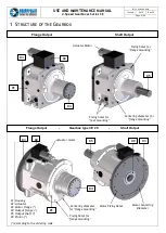
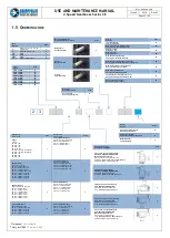
1  Structure of the Gearbox ___________________________________________________ 6


1.1  Delivery conditions _________________________________________________________________ 7 
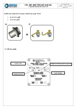
1.2  Data label ________________________________________________________________________ 8 
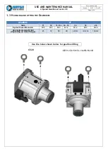
1.3  Handling and lifting the Gearboxes ___________________________________________________ 9 
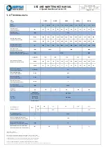
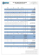
1.4  Technical data ___________________________________________________________________ 10 
1.5  Ordering code ____________________________________________________________________ 12 
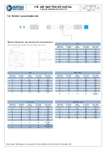
1.6  Motor flange dimensions ___________________________________________________________ 13 

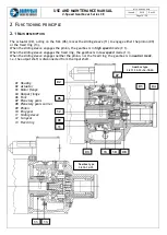
2  Functioning principle _____________________________________________________ 14


2.1 Main description  __________________________________________________________________ 14 

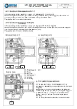
2.2.1 Gearbox in high speed mode (1:1) _______________________________________________  15


2.2.2 Gearbox in low speed mode (1:i) ________________________________________________  15


2.2.3 Gearbox in neutral mode ______________________________________________________  15


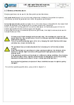
2.2 General operating rules ____________________________________________________________ 16 

3  Gearbox start-up _________________________________________________________ 17


3.1  Motor specifications _______________________________________________________________ 17 

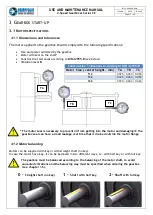
3.1.1 Dimensions and tolerances _____________________________________________________  17


3.1.2 Motor balancing ______________________________________________________________  17


3.1.3 Matching motor - gearbox balancing _____________________________________________  18


3.1.4 Screws tightening torque ______________________________________________________  18


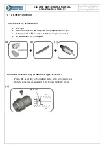
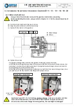
3.2  Assembling the motor on the gearbox - Gearbox CE 11 - 13 - 13+ - 16 - 18 - 20  _____________ 19 

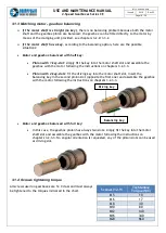
3.2.1 Motor shaft with key __________________________________________________________  19


3.2.2 Motor shaft without key (straight shaft) - conical clamping unit ______________________  20


3.2.3 Disassembling the clamping unit (100) from motor shaft ____________________________  23


3. 3  Assembling the motor on the gearbox - Gearbox type CE 12 - 14 - 15 _____________________ 24 

3.3.1 Motor shaft with key __________________________________________________________  24


3.3.2 Motor shaft without key (straight shaft) - conical clamping unit ______________________  26


3.3.4 Assembling the gearbox on the motor ____________________________________________  27


3.4 Motor-gearbox assembling options  ___________________________________________________ 28 
3.5  Gearbox Output __________________________________________________________________ 29 

3.5.1 Verifying gearbox output loading capacity ________________________________________  29


3.5.2 Gearbox output bearings: position and loading capacity ____________________________  30


4  Assembling positions and lubrication  _______________________________________ 31


4.1  Choosing the lubrication mode ______________________________________________________ 31 
4.2  Splash Lubrication  ________________________________________________________________ 32 

4.2.1 Monitoring the oil level: Oil Sight-glass and Oil Level Sensor _________________________  32


4.3  Oil Recirculating Lubrication (Forced Lubrication)  _____________________________________ 34 

4.3.1 Monitoring the oil flow: Oil Flow Rate Switch _____________________________________  35


4.3.2 Dimensioning oil cooling systems - cooling power __________________________________  35


4.4 Gearbox assembling designation _____________________________________________________ 36 
4.5 Lubrication examples ______________________________________________________________ 36 

4.5.1 CE 13 - Horizontal assembly - Forced Lubrication With Suction Pump  _________________  37


4.5.2  CE 13 - Horizontal assembly - Forced Lubrication With Oil Return By Fall Down ________  37


4.5.3  CE 13 - Vertical Down Assy - Forced Lubrication With Oil Return By Suction  ___________  38


4.5.4  CE 13 - Horizontal Assy - Forced Lubrication With Oil Return By Fall Down  ____________  38


4.5.5  CE 20 - Horizontal Assembly - Forced Lubrication With Suction Pump _________________  39


4.5.6  CE 20 - Horizontal Assembly - Forced Lubrication With Oil Return By Fall Down ________  39


4.5.7  CE 20 - Horizontal Assembly - Forced Lubrication With Oil Return By Fall Down ________  40


4.5.8  CE 20 - Horizontal Assembly - Forced Lubrication With Suction Pump _________________  40


4.5.9 CE 20 - Vertical Down Assembly - Forced Lubrication With Suction Pump ______________  41


4.5.10  CE 20 Vertical Down Assy - Forced Lubrication With Oil Return By Fall Down  _________  41


4.6  Assembling Positions & Lubrication - CE 11 ____________________________________________ 42 
4.7  Assembling Positions & Lubrication - CE 12 ____________________________________________ 44 
4.8  Assembling Positions & Lubrication - CE 13 & CE13+ ____________________________________ 46 
4.9  Assembling Positions & Lubrication - CE 14 & CE 15  ____________________________________ 48


Summary of Contents for CE 11

Page 1: ...USE AND MAINTENANCE MANUAL 2 Speed Gearboxes Series CE M CE GEN ENG DOCX Issued 2018 Rev 03 Page 1 59 USE AND MAINTENANCE MANUAL CE 2 Speed Gearboxes ...

Page 2: ...USE AND MAINTENANCE MANUAL 2 Speed Gearboxes Series CE M CE GEN ENG DOCX Issued 2018 Rev 03 Page 2 59 ...

Page 3: ...bol highlights critical operations a wrong procedure can cause damages to the gearbox non observance can impair operator s safety All gearboxes are delivered without oil Always make sure that a proper lubrication is applied to the gearbox according to the ordered code Operating the gearbox for long periods in high speed mode can produce a local damage on the engaged teeth of the gears This may tur...

Page 4: ...ing unit______________________ 26 3 3 4 Assembling the gearbox on the motor____________________________________________ 27 3 4 Motor gearbox assembling options ___________________________________________________28 3 5 Gearbox Output __________________________________________________________________29 3 5 1 Verifying gearbox output loading capacity ________________________________________ 29 3 5 2 ...

Page 5: ..._________________________54 5 Electrical Section ________________________________________________________ 55 5 1 Actuator__________________________________________________________________________55 5 2 Circuit Diagram ___________________________________________________________________55 5 3 Flow Chart Iso Program Example ___________________________________________________56 6 Gearbox Layout Views ...

Page 6: ...OX 02 04 01 04 02 01 03 03 Fixing holes for feet mounting Actuator Motor Centering diameter for flange mounting Fixing holes for flange mounting Centering diameter for flange mounting 09 Motor Fixing Holes 05 Motor Centering Diameter 03 Actuator motor 01 Housing 02 Actuator 03 Motor flange 04 Output flange 05 Output shaft 09 Pinion according to the ordering code 05 Fixing holes for flange mounting...

Page 7: ... connector a complete with plug and relevant pins Balancing insert b for motor shaft balancing if necessary Oil level sensor c on request Additional components only for Gearboxes type CE 12 14 15 Pinion d according to the ordered motor with o ring and screw Only for some motors spacer 17 to be inserted in the pinion 1 1 DELIVERY CONDITIONS a b c Spacer 17 d ...

Page 8: ...xes Series CE M CE GEN ENG DOCX Issued 2018 Rev 03 Page 8 59 Additional components only for Gearboxes type CE 20 Drain fitting e Vent fitting f 1 2 DATA LABEL e f Code see Ordering Code on page 10 Serial Number Gearbox Size Transmission ratio ...

Page 9: ... 59 CE 11 12 13 13 14 15 16 18 CE 20 1 3 HANDLING AND LIFTING THE GEARBOXES GEARBOX CE Size 11 12 13 13 14 15 16 18 20 Eyebolt hole dimension M10 M10 M10 M12 M12 M12 M20 Approximate weight kg depending on motor flange 45 50 80 90 190 230 190 230 190 230 Use the holes shown below for gearbox lifting ...

Page 10: ...co massimo radiale X mm 0 03 Max axial backslah Gioco assiale massimo Y mm 0 25 Max vibration value Valore massimo vibrazioni mm s 1 At test run speed A velocità riferimento test RPM 6000 Weight ca Peso circa kg 45 65 80 88 90 Oil Type Tipo Olio Splash Lubr Lubr sbattimento ISO VG68 Forced Lubr Lubr forzata ISO VG46 Forced lubr Lubr Forzata ISO VG32 Oil fil volume Volume d olio dm B5 0 6 1 1 2 1 2...

Page 11: ...e massimo 1 mm s Max vibration value Valore massimo vibrazioni 6000 5000 At test run speed A velocità riferimento test 95 190 230 200 230 205 240 kg Weight ca Peso circa ISO VG68 Splash Lubr Lubr sbattimento Oil Type Tipo Olio ISO VG46 Forced Lubr Lubr forzata ISO VG32 Forced lubr Lubr Forzata 3 3 B5 dm Oil fil volume Volume d olio 1 5 V1 5000 h Oil change interval Intervallo cambio olio 120 C Max...

Page 12: ...4 L 110 Ød 55 k 100 CE 15 L 110 Ød 55 k 100 CE 16 L 140 Ød 65 k 125 CE 20 L 140 Ød 65 k 125 2 Shaft with double key Albero doppia chiavetta CE 13 L 110 Ød 48 k 90 CE 13 L 110 Ød 55 k 100 CE 14 L 110 Ød 55 k 100 CE 15 L 110 Ød 55 k 100 6 Shaft witout key Albero liscio senza chiavetta CE 12 L 80 Ød 42 k CE 13 L 110 Ød 48 k CE 13 L 110 Ød 55 k CE 14 L 110 Ød 55 k CE 15 L 110 Ød 55 k CE 16 L 140 Ød 65...

Page 13: ...Lunghezza Centering Centraggio Pitch holes Interasse fori d L D D1 0 42 110 250 300 1 55 110 230 265 2 55 110 300 350 3 60 140 300 350 4 48 110 250 300 5 48 110 230 265 6 55 110 250 300 7 42 110 300 350 8 42 110 230 265 A 55 110 280 325 B 60 140 350 400 Øext 450 8 holes CE14 CE15 Motor Code Codice motore Diameter Diametro Lenght Lunghezza Centering Centraggio Pitch holes Interasse fori d L D D1 0 ...

Page 14: ...peed mode 1 1 When the sliding sleeve engages the fixed ring the gearbox is in low speed mode 1 i When the sliding sleeve engages neither the pinion nor the fixed ring the gearbox is in neutral mode i e the output shaft is disconnected from the input shaft 01 Housing 02 Actuator 03 Motor flange 04 Output flange 06 Fork 07 Planetary gears 08 Planetary gears carrier 09 Pinion 10 Ring gear 11 Sliding...

Page 15: ... the motor goes to the planetary unit through the sun gear 12 while the ring gear 10 is still because it is engaged with the fixed ring 13 The gearbox is in 1 i mode reduction mode 2 2 3 Gearbox in neutral mode In this operating mode the sliding sleeve 11 is engaged neither with the pinion 09 nor with the fixed ring 13 Motion coming from the motor goes to the planetary unit through the sun gear 12...

Page 16: ...d noise over time For all other operating specifications please refer to chapter 5 3 In order prevent teeth damages and increased noise it is mandatory to switch to low speed mode for a few seconds every 1 hour of continuous operation in high speed mode whatever the speed is This will cause the planetary gears 7 to turn changing the teeth that transmit torque and allowing a proper lubrication too ...

Page 17: ...he gearbox seal can have a small leakage over time that is drained outside the motor flange 3 1 2 Motor balancing Motors can be supplied with key or with straight shaft no key In case the motor has a key it can be balanced in two different ways i e with half key or with full key The gearbox must be balanced according to the balancing of the motor shaft to avoid unwanted vibrations and the balancin...

Page 18: ...owing the instructions on chapters 3 2 3 3 Pinion with 2 key slots fit the driving key into the motor shaft slot insert the balancing key in the second pinion slot opposite the first one and assemble the gearbox with the motor following the instructions on chapters 3 2 3 3 Motor and gearbox balanced with full key In this case the gearbox pinion has always two slots simply fit the key into the moto...

Page 19: ...n Gearboxes type CE11 13 16 18 20 for motors with key come as a complete unit that must not be disassembled not even if the screws must be changed see above Do not remove the motor flange from the gearbox the seal might be damaged Longer screws and nuts The gearbox flange 03 is fixed to the gearbox housing by means of screws If the PCD of the flange fixing screws is the same as the PCD of the moto...

Page 20: ...re in position X d Insert the pinion group unit 100 with motor interface flange 03 on the motor shaft e Push both pinion 100 and screws 9a until the gearbox flange is against the motor surface A To allow clampers 15 to slide and prevent them from getting stuck screws heads should always be kept about 2 mm from the pinion 9 surface and the sectors should always be in position X during motor shaft i...

Page 21: ...to the motor shaft avoiding axial sliding of the pinion during the clampers 15 tightening pay attention at this step in fact the axial slidings of the pinion might generate troubles at the bearing 98 h Tighten the screws 9a by hand after removing set screws 14 if present i Gradually fasten the screws step by step till the right tightening torque is reached see chapter 3 1 4 j Remove the set screws...

Page 22: ...r 12 with the planets 07 m Tighten the screws see chapter 3 2 1 d for the possible configurations Step 3 When inserting the sun gear 12 inside the planetary unit pay attention not to damage the gears as this would result in increased noise during operation If you feel that the gears do not engage smoothly slowly turn the output shaft 04 by hand until the sun gear engages properly 100 12 07 04 O ri...

Page 23: ...on until the sun gear is out of the gearbox c Remove the screws that fix the motor flange to the motor d Loosen the screws 9a of the clamping sectors 15 for about 2 mm e With a hammer hit the head of the screws of the clamping sectors 9a one by one at 180 in order to release the clamping sectors and make disassembling operations possible f As shown in the picture below you may need to use an extra...

Page 24: ...element therefore it must be assembled on the motor as shown in picture a For all other motors the flange must be assembled as shown in picture b or picture c a b c For horizontal mounting the drain hole 3c on the motor flange 03 must be at the bottom ASSEMBLING THE PINION ON THE MOTOR SHAFT Fit the pinion 09 on the motor shaft together with plug O ring 18 and spacer 17 only if necessary Only for ...

Page 25: ...rilling the hole place the O ring 09d on the pinion spot facing and tighten the locking screw 09c until the screw head is in contact with the pinion Assembling dimension Y CE 12 101 5 mm CE 14 15 138 mm Size Ø A mm B mm CE 12 6 75 4 CE 14 15 8 5 5 Option a see Step 1 A B Make sure that the pinion is completely inserted on the motor shaft 09c 09d 09c 09d Option b and c see Step 1 Step 3 After fitti...

Page 26: ...urfaces on both pinion and motor shaft d Assemble the pinion 22 with the clamping ring 23 on the motor shaft against bush 21 e Tighten the screws 22a by hand to lock the clamping system f Tighten the screws 22a step by step by means of a torque wrench one opposite the other to the torque indicated in the chart below Don t use Molybdenum Disulphide lubricants to prevent slipping of the clamping uni...

Page 27: ... 03 Page 27 59 3 3 4 Assembling the gearbox on the motor Check that the O Ring 01a is in place Assemble motor flange pinion to the gearbox so that the free end of the pinion 09 or 22 fits the spline of the sun gear 12 After assembling check that the gearbox rotation is free 01a 12 09 or 22 ...

Page 28: ...reduce the vibrations it is strongly suggested to additionally fix the motor by means of its feet In this case use shims under the motor feet shown in red color upon customer s supply that must be adapted by grinding after checking their thickness during assembling operations Below are the options available Gearbox flange mounting Gearbox flange mounting motor feet Gearbox feet mounting Gearbox fe...

Page 29: ... between the output bearings so that the load is proportionally held by both of them It is always necessary to verify the gearbox bearings life referring to the data indicated on chapter 3 5 2 In case the bearings life is too low it is necessary to modify the machine design so that the radial force is better distributed on the gearbox output bearings If this is not possible the machine should be e...

Page 30: ... ECP 114 000 NU 2211 ECP 114 000 CE16 NUP 2111 EC 114 000 NU 2211 ECP 114 000 RNU 2211 ECP 114 000 CE18 NUP 2213 ECP 170 000 NU 2213 ECP 170 000 NU 2213 ECP 170 000 CE20 21314 E 285 000 NU 314 ECP 236 000 NU 314 ECP 236 000 Angular contact bearings Cuscinetti a contatto obliqui CE13 7210 BEGAP 40 000 7210 BEGAP 40 000 X X CE13 7211 BEGAP 49 000 7211 BEGAP 49 000 X X CE14 7211 BEGAP 49 000 7211 BEG...

Page 31: ... oil supply unit that ensures a continuous oil recirculation This continuous oil flow produces a better lubrication of the inner parts and improves the heat dissipation For these reasons this way of lubrication is used In case of continuous rotation at high speeds and with short downtimes It is also used in some assembly positions even if the speeds and operating times are not high because it is t...

Page 32: ...to ISO VG 68 it must be compatible with sealing elements it must have good resistance to aging and it should develop a high protection towards corrosion and wear Suitable assembling positions for Splash Lubrication CE 11 CE 12 CE 13 13 CE 14 15 CE 16 18 20 Horizontal standard Maximum input speed 4500 rpm B5 OPP YES YES YES YES NO Horizontal turned Maximum input speed 4500 rpm B5 OPP YES YES YES YE...

Page 33: ...n order to keep the oil level under control over time it is strongly suggested to use an additional oil level sensor c assembled on the gearbox upon request Baruffaldi can supply a suitable sensor code 999 912 06547 Fill the gearbox with oil until it reaches the middle of the oil sight glass h or the oil level sensor when supplied c NO Normally Open sensor output is open in air and closed in the p...

Page 34: ...ve inner diameter Ø min 20 mm Oil back pressure in the return pipe from the gearbox must beavoided A 60 μm filter and a pressure limitation valve on the oil supply unit should also be used as a safeguard Overall rate for CE 11 12 13 13 14 15 is 1 5 L min Overall rate for CE 16 18 20 is 3 L min Whenever a further reduction in working temperature is required or if it is necessary to keep the gearbox...

Page 35: ...ox The heat developed must be removed from the gearbox in order to have steady temperatures moreover it can be necessary to keep the unit at low temperatures to avoid elongations and bendings that could damage the machine or affect its precision In the following chart the heating power to be removed by the cooling system is indicated for all gearbox sizes This data can be used for any kind of cool...

Page 36: ...A V3 Vertical upward 4 4 GEARBOX ASSEMBLING DESIGNATION The different assembling positions on the machine are identified with a specific code ase described below 4 5 LUBRICATION EXAMPLES In the following pages some examples of lubrication layouts are shown for some gearbox sizes Changing the connection points these examples can be used as a reference for all gearbox sizes ...

Page 37: ...L 2 Speed Gearboxes Series CE M CE GEN ENG DOCX Issued 2018 Rev 03 Page 37 59 4 5 1 CE 13 Horizontal assembly Forced Lubrication With Suction Pump 4 5 2 CE 13 Horizontal assembly Forced Lubrication With Oil Return By Fall Down ...

Page 38: ...2 Speed Gearboxes Series CE M CE GEN ENG DOCX Issued 2018 Rev 03 Page 38 59 4 5 3 CE 13 Vertical Down Assy Forced Lubrication With Oil Return By Suction 4 5 4 CE 13 Horizontal Assy Forced Lubrication With Oil Return By Fall Down ...

Page 39: ...L 2 Speed Gearboxes Series CE M CE GEN ENG DOCX Issued 2018 Rev 03 Page 39 59 4 5 5 CE 20 Horizontal Assembly Forced Lubrication With Suction Pump 4 5 6 CE 20 Horizontal Assembly Forced Lubrication With Oil Return By Fall Down ...

Page 40: ...L 2 Speed Gearboxes Series CE M CE GEN ENG DOCX Issued 2018 Rev 03 Page 40 59 4 5 7 CE 20 Horizontal Assembly Forced Lubrication With Oil Return By Fall Down 4 5 8 CE 20 Horizontal Assembly Forced Lubrication With Suction Pump ...

Page 41: ... 2 Speed Gearboxes Series CE M CE GEN ENG DOCX Issued 2018 Rev 03 Page 41 59 4 5 9 CE 20 Vertical Down Assembly Forced Lubrication With Suction Pump 4 5 10 CE 20 Vertical Down Assy Forced Lubrication With Oil Return By Fall Down ...

Page 42: ...USE AND MAINTENANCE MANUAL 2 Speed Gearboxes Series CE M CE GEN ENG DOCX Issued 2018 Rev 03 Page 42 59 4 6 ASSEMBLING POSITIONS LUBRICATION CE 11 ...

Page 43: ...USE AND MAINTENANCE MANUAL 2 Speed Gearboxes Series CE M CE GEN ENG DOCX Issued 2018 Rev 03 Page 43 59 ...

Page 44: ...ANUAL 2 Speed Gearboxes Series CE M CE GEN ENG DOCX Issued 2018 Rev 03 Page 44 59 4 7 ASSEMBLING POSITIONS LUBRICATION CE 12 In position B and B1 injectors are fitted for lubrication oil Do not remove or turn seizing danger ...

Page 45: ...USE AND MAINTENANCE MANUAL 2 Speed Gearboxes Series CE M CE GEN ENG DOCX Issued 2018 Rev 03 Page 45 59 In position B and B1 injectors are fitted for lubrication oil Do not remove or turn seizing danger ...

Page 46: ...USE AND MAINTENANCE MANUAL 2 Speed Gearboxes Series CE M CE GEN ENG DOCX Issued 2018 Rev 03 Page 46 59 4 8 ASSEMBLING POSITIONS LUBRICATION CE 13 CE13 ...

Page 47: ...USE AND MAINTENANCE MANUAL 2 Speed Gearboxes Series CE M CE GEN ENG DOCX Issued 2018 Rev 03 Page 47 59 ...

Page 48: ...AL 2 Speed Gearboxes Series CE M CE GEN ENG DOCX Issued 2018 Rev 03 Page 48 59 4 9 ASSEMBLING POSITIONS LUBRICATION CE 14 CE 15 In position B and B1 injectors are fitted for lubrication oil Do not remove or turn seizing danger ...

Page 49: ...USE AND MAINTENANCE MANUAL 2 Speed Gearboxes Series CE M CE GEN ENG DOCX Issued 2018 Rev 03 Page 49 59 In position B and B1 injectors are fitted for lubrication oil Do not remove or turn seizing danger ...

Page 50: ...USE AND MAINTENANCE MANUAL 2 Speed Gearboxes Series CE M CE GEN ENG DOCX Issued 2018 Rev 03 Page 50 59 4 10 ASSEMBLING POSITIONS LUBRICATION CE 16 18 ...

Page 51: ...USE AND MAINTENANCE MANUAL 2 Speed Gearboxes Series CE M CE GEN ENG DOCX Issued 2018 Rev 03 Page 51 59 ...

Page 52: ...USE AND MAINTENANCE MANUAL 2 Speed Gearboxes Series CE M CE GEN ENG DOCX Issued 2018 Rev 03 Page 52 59 4 11 ASSEMBLING POSITIONS LUBRICATION CE 20 ...

Page 53: ...USE AND MAINTENANCE MANUAL 2 Speed Gearboxes Series CE M CE GEN ENG DOCX Issued 2018 Rev 03 Page 53 59 ...

Page 54: ...SE AND MAINTENANCE MANUAL 2 Speed Gearboxes Series CE M CE GEN ENG DOCX Issued 2018 Rev 03 Page 54 59 4 12 ASSEMBLING POSITIONS LUBRICATION CEA13 CEA 13 4 13 ASSEMBLING POSITIONS LUBRICATION CEA14 CEA 15 ...

Page 55: ...d neutral positions The unit is designed according to the easiest and most durable solutions for the speed change 5 2 CIRCUIT DIAGRAM The following circuit is the best solution in order to preserve the motor and to avoid the delays due to the actuator motor inertia The power supply unit must be able to supply at least 6A in order to allow clutch slipping and to be able to overcome static friction ...

Page 56: ...USE AND MAINTENANCE MANUAL 2 Speed Gearboxes Series CE M CE GEN ENG DOCX Issued 2018 Rev 03 Page 56 59 5 3 FLOW CHART ISO PROGRAM EXAMPLE ...

Page 57: ... IF M41 switch 1 more than 2 sec THEN Attempt 9 Gear shift stop command Spindle stop oscillation command ELSE IF M42 switch 0 more than 2 sec THEN Gear shift stop command Wait for 0 3 sec optional but recommended Gear shift reverse command IF M41 switch 1 THEN Gear shift stop command Wait for 0 3 sec optional but recommended Attempt Attempt 1 ENDIF ELSE IF M42 switch 1 THEN Gear shift stop command...

Page 58: ...2 Actuator 03 Motor flange 04 Output flange or Output shaft 06 Fork 07 Planetary gears 08 Planetary gears carrier 09 Pinion 10 Ring gear 11 Sliding sleeve 12 Sun gear 13 Fixed ring 02 A Rotary Shaft Seal pinion B Pinion Bearing C Rotary Shaft Seal output D Output Shaft Bearing outer E Output Shaft Bearing inner F Ring Gear Bearing 06 07 04 08 11 09 10 12 13 01 03 A B C D E F ...

Page 59: ...1 03 A C D E F B 01 Housing 02 Actuator 03 Motor flange 04 Output flange or Output shaft 06 Fork 07 Planetary gears 08 Planetary gears carrier 09 Pinion 10 Ring gear 11 Sliding sleeve 12 Sun gear 13 Fixed ring 02 A Rotary Shaft Seal pinion B Pinion Bearing C Rotary Shaft Seal output D Output Shaft Bearing outer E Output Shaft Bearing inner F Ring Gear Bearing ...

Reviews: