USE AND MAINTENANCE MANUAL
2-Speed Gearboxes Series CE
M
.CE.GEN.ENG.DOCX
Issued
2018
Rev.03
Page 24 / 59
3.
3
A
SSEMBLING THE MOTOR ON THE GEARBOX
-
G
EARBOX TYPE
CE
12
-
14
-
15
For gearboxes type CE12 and CE14-CE15, the procedure is different from all other gearboxes.
3.3.1 Motor shaft with key
•
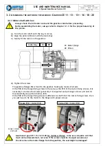
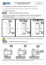
ASSEMBLING THE MOTOR FLANGE ON THE MOTOR
Some motors have fixing holes that are in the same position as those for fixing the motor flange to the
gearbox. In this case, the flange is only a centering element, therefore it must be assembled on the
motor as shown in picture
a).
For all other motors, the flange must be assembled as shown in picture
b)
or picture
c)
.
a)
b)
c)
For horizontal mounting, the drain hole (3c) on the motor flange (03) must be at the bottom.
•
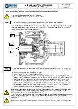
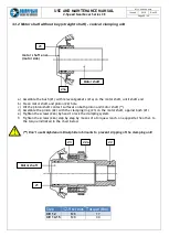
ASSEMBLING THE PINION ON THE MOTOR SHAFT
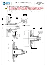
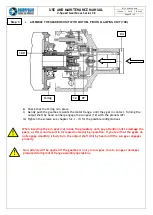
Fit the pinion (09) on the motor shaft, together with plug+O-ring (18) and spacer (17 - only if necessary).
Only for very small motor shafts, there can be an adaptation bush (19), that must be fixed on the motor
shaft by means of a screw (19a), to be locked with the relevant sealing ring (19b).
03
Step 2
Step 1
hex screw
hex nut
3c
03
03
3c
3c
18
18
Motor shaft
17
Motor shaft
19
19b
19a
Motor shaft
stud bolt

