USE AND MAINTENANCE MANUAL
2-Speed Gearboxes Series CE
M
.CE.GEN.ENG.DOCX
Issued
2018
Rev.03
Page 35 / 59
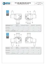
4.3.1 Monitoring the oil flow: Oil Flow Rate Switch
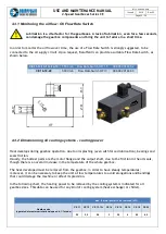
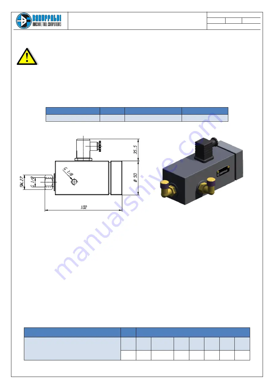
In order to monitor the oil flow over time, the use of a Flow Rate Switch is strongly suggested, to be
connected to the oil supply circuit. Upon request, Baruffaldi can provide a suitable Flow Rate Switch, as
shown below.
4.3.2 Dimensioning oil cooling systems - cooling power
Heat develops during gearbox operation, due to oil splashing (even with forced lubrication), bearings and
seals friction.
Usually, the hottest parts are the motor flange and the output shaft, due to the friction in the oil seals,
though there is an overall increase in the temperature of the whole gearbox.
The heat developed must be removed from the gearbox, in order to have steady temperatures;
moreover, it can be necessary to keep the unit at low temperatures to avoid elongations and bendings
that could damage the machine or affect its precision.
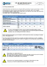
In the following chart, the heating power to be removed by the cooling system is indicated for all
gearbox sizes. This data can be used for any kind of cooling system (heat exchanger or chiller).
CE 11-12-13-13+-14-15
1,50 l/min Flow Rate Switch
OFI 1.5
996.002.01468.2
CE 16-18-20
3,00 l/min
Flow Rate Switch OFI 3
996.002.01468.3
Max. thermal power to be removed (kW)
Gearbox size
(operated at maximum rotational speed in 1:1 mode)
CE 11
CE 12
CE 13-13+
CE 14
CE 15
CE 16
CE 18
CE 20
2,5
2,5
2,8
3
3,2
4
5,5
6,5
Lubrication is a vital factor for the gearboxes. A lack of lubrication, even for a few seconds,
can damage the gearbox components and bring the unit to failure in a short time.

