background image

4

NOTE: Do not place directly on vapor barrier. Elevation is required to allow the condensate water to 
drain via gravity. 

If the unit is handled in such a manner that the compressor did not remain in the upright position, you 
will need to place it on a level surface and wait a minimum of 2 hours before turning the unit "on".

Step

 #

1

Place


dehumidifier


on


a


level


surface

.

Step #2: Set Up Drain Line

The


drain


line


should


be


routed


to


a


suitable


drain


on


the


outside

It


must


flow


down


to


the


drain


without


any


loops

dips

or


valleys

.

1

Cut


a


piece


of


3

/

4

OD


PVC


that


is


approx.


6

long

.

2

Insert


PVC


into


a


3

/

4

elbow

then


attach


to


a


3

/

4

OD


length


of


PVC


to


drain

.

(

Note

Keep


the


length


of


PVC


drain


pipe


to


a


minimum

).

3

Insert


the


open


end


of


the


tubing


into


the


3

/

4"


pipe


so


that


it


does


not


extend


into


the


elbow


fitting.


For


proper


flow

a


minimum


downward


slope


of


1

per


10'


run


is


required

. ( 

Note

If


a


proper


downward


angle


is


not


possible

then


it


is


recommended


to


use


an


AirWerx


90


which


includes


an


integrated


pump 

or utilize


an


external


condensate


pump

).

5

Always


test


the


drain


before


leaving


the


installation


area

.

4

Support


the


PVC


tubing


so


that


it


maintains


a


smooth


downward


flow


to


drain

.

Recommended


Drain


Option

-

Transition


to


PVC


Pipe

Drain Tube - 12 inches Long. 12mm OD.

Step

 #

3

Plug


unit


into


15


amp


grounded


circuit

.

Summary of Contents for AirWerx 90

Page 1: ...Tel 1 888 641 8862 Web www baseaire com E mail sales baseaire com Installation Operations Manual AirWerx 90 Patented Specifications subject to change without notice ...

Page 2: ......

Page 3: ...lectrical Supply Principle of Operation Installation Key Functions Indicator Lights Remote Control Operating Instructions Diagram Maintenance Dehumidifier Storage Ducted Applications Troubleshooting Spare Parts Warranty Information 2 2 3 3 3 3 5 6 6 7 8 8 9 9 10 11 12 1 ...

Page 4: ...e and the discharge requires a minimum of 36 clearance AirWerx Dehumidifiers should only be maintained and repaired by a qualified technician AirWerx Dehumidifiers are only intended for operation when oriented with the unit sitting on its feet and level Operating the unit in any other orientation could allow water to flood electrical components If there is a chance that water flooded the dehumidif...

Page 5: ...njury from electric shock 2 Only plug unit into grounded electrical circuit 3 Do not use an extension cord 4 Do not use a plug adapter Principle of Operation The AirWerx Series Dehumidifier utilizes its integral humidistat to monitor the conditioned space When the relative humidity goes above the selected set point the dehumidifier will energize Air is drawn across an evaporator coil which is cool...

Page 6: ...at is approx 6 long 2 Insert PVC into a 3 4 elbow then attach to a 3 4 OD length of PVC to drain Note Keep the length of PVC drain pipe to a minimum 3 Insert the open end of the tubing into the 3 4 pipe so that it does not extend into the elbow fitting For proper flow a minimum downward slope of 1 per 10 run is required Note If a proper downward angle is not possible then it is recommended to use ...

Page 7: ...midity levels displayed are approximate only 5 3 Continuous Mode successfully switched into continuous mode The display screen will show CO would like to switch back to normal humidistat operation simply move the setpoint above 35 To switch into continuous mode simply use the down arrow to set the humidity below 35 The Cont light should illuminate green on the display board to indicate that you ha...

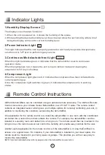
Page 8: ...ace the remote could be mounted in your living space or garage This provides you with an easy way to monitor the dehumidifier NOTE Symbols indicated below will only appear when the dehunidifier is powered on Remote Control Instructions 1 Humidity Display Screen The display screen has two functions 2 Power Indicator Light 3 Continuous Mode autodefrost Light This light indicates that the unit is pro...

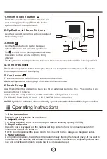
Page 9: ...wn arrow buttons to adjust the humidity level 1 On off power button 2 Up Button Down Button Use the Mode button to switch between dehumidification and a ducted application 3 Mode The symbol on the display board indicates the sensor on the remote control is being utilized The symbol on the display board indicates the sensor on the dehumidifier is being utilized 4 Temperature Press the temperature butt...

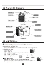
Page 10: ... the filter mesh by vacuuming or washing with warm water no soap or solvents 4 Be sure filter is completely dry before restarting the unit Coil Maintenance Once per year clean the coils with an approved coil cleaner Coil cleaner should be a self rinsing foaming cleaner such as WEB Coil Cleaner Cleaning the filter Power cord Inlet End Cap Unit Cover Handle Air Intlet Grille Drain Hose Control panel...

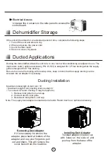
Page 11: ...rewed into an adapter if necessary Ducting Installation Maximum total length of duct run 10 To connect 12 return ducting it may be helpful to 2 Connect duct to inlet grille 3 Reconnect inlet grille to end cap Note The supply duct adapter is standard on all units Return duct is an optional accessory Maximum length if only ducting inlet or outlet 6 1 Remove inlet grille from end cap Installing Duct ...

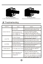
Page 12: ...Machine Won t Run Low Air Flow Trouble Code E1 Loud Noise Filter Mesh is Blocked E1 Humidity Sensor Issues Room Temperature Over 104 or Below33 8 Display LO Machine Is Not level Move the dehumidifier to flat firm ground Clean the filter mesh according to instructions listed in manual Check to ensure that wire is connected at both ends If no issues are visible the sensor may be faulty The unit is o...

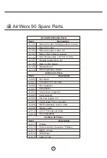
Page 13: ... A 916 A 917 A 918 A 919 A 900 A 901 A 902 Prefilter Filter Assembly Cassette Prefilter MERV 8 Filter HEPA Filter Carbon Filter Fan Motor Complete Fan Assembly Fan Capacitor AirWerx 90 Filters Part Description 11 A 106 Duct Kit Assembly W 103 W 100 A 107 Flexible Supply Duct 72 A 903 A 904 A 905 Compressor Compressor Capacitor Coil Assembly A 906 Hot Gas Bypass Coil Condensate Pump Assembly A 907 ...

Page 14: ...ouse BaseAire will have an initial inspection If it is determined to be invalid warranty claim see exclusions below customers have to pay for all associated repair costs and shipping costs for units repair All warranty benefits apply to the original owner only Warranty cannot be transferred or assigned 5 YEARS FROM DATE OF PURCHASE BaseAire warrants the compressor condenser and evaporator will ope...

Page 15: ...RTH ARE IN LIEU OF ALL OTHER WARRANTIES EXPRESSED OR IMPLIED IN LAW OR IN FACT INCLUDING IMPLIED WARRANTIES OF MERCHANTABILITY AND FITNESS FOR PARTICULAR PURPOSE BaseAire s total liability regardless of nature of claim shall not exceed original purchase exceed original purchase price of the product if a product or component is replaced while under warranty the applicable warranty period shall not ...

Page 16: ...Scan QR Code to Register Warranty ...

Reviews: