SANIDRY CSB INSTALLER'S AND OWNER'S MANUAL
2
SaniDry CSB Installer’s & Owner’s Manual
3
SaniDry CSB Installer’s & Owner’s Manual
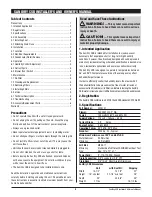
4. Unit Assembly
4.1 Installing Feet (Optional)
Included with your SaniDry
CSB are four leveling feet. It is
important to level the unit for
proper draining. (See section
5.1.4, Figure 6)
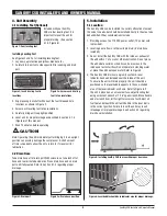
Installing Leveling Feet
See Figures 2 and 2a for installing leveling feet.
1. Lay down a protective pad (pillow, blanket, etc.).
2. Carefully turn unit onto side opposite filter opening and drain
port.
3. Align leveling foot shaft with one of the four threaded hole
locations as shown in Figure 2.
4. Screw each leveling foot in ten revolutions.
5. Carefully bring unit to upright position.
6. Level unit for proper drainage as described in section 5.1.4
(Figure 6) of this manual.
7. Wait 10 minutes before operating.
CAUTION!
Note: Operating the unit immediately after bringing it to an upright
position can possibly damage the compressor. A short amount
of time is needed to allow the oil to return to it’s reservoir for
lubrication.
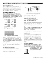
4.2 Drain Hose
Take drain hose off of drain port. With scissors, cut one inch off of
hose end to eliminate dented area. Place drain hose end on drain
port until fully seated. Refer to Section 5.1.4 regarding proper
drainage.
5. Installation
5.1 Location
The SaniDry CSB can be installed in a variety oflocations to meet
the owner’s needs, but should beinstalled directly in the area to be
dehumidified. Other considerations include:
1. Providing access to a 115 VAC power outlet (10' power cord
is provided).
2. Locating near a floor or other suitable drain (8' drain hose
included).
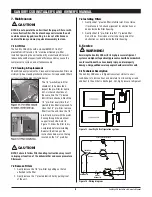
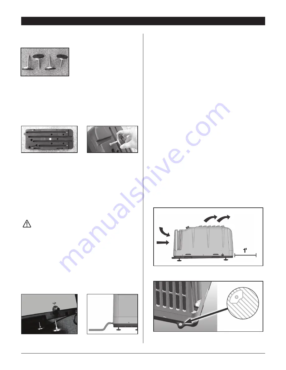
3. Do not install the SaniDry CSB with the intake or exhaust of
the unit within 1' of a wall or other obstruction. Do not place
the unit where curtains or debris can be drawn onto the
intake and restrict airflow. Do not operate in standing water
or place the unit near open water. Refer to Figure 5.
4. The SaniDry CSB drains via a gravity system. A level
indicator has been included near the intake of the unit.
To ensure the unit will drain properly, the unit should be
positioned so the level bubble appears in the non-shaded
area of the level indicator as shown. Refer to Figure 6. If
the unit is placed on an unlevel surface, adjust leveling feet
using a crescent wrench or 7/16" open wrench. Move handle
end of wrench from left to right to lower one foot. Adjust all
four feet underneath the unit until bubble in the level dial is
in the correct position. Failure to level the unit may result
in leakage or improper drainage. See Section 4.2 regarding
drain hose installation.
Figure 2: Insert leveling feet in
locations
Figure 2a: Screw each leveling
foot in ten revolutions
Figure 1: Four leveling feet
Figure 3: Drain port
Figure 2a: Drain hose position
Figure 5: Installing SaniDry CSB in area with proper clearance.
Figure 6: Level bubble should be in indicator area for proper drainage.


