Table of Contents
1. Specifications ................................................................................... 2
2. Installation ........................................................................................ 3
2.1 Location .................................................................................... 3
2.1A In Humid Area, No Ducting ................................................... 3
2.1B In Humid Area, Duct Inlet and/or Outlet .................................... 3
2.1C In Remote Area, Duct Inlet & Outlet ...................................... 3
2.1D In Remote Area, Duct Outlet Only ......................................... 3
2.1E In Remote Area, Duct Inlet Only ............................................ 3
2.2 Electrical Requirements ............................................................ 3
2.3 Condensate Removal ................................................................ 3
2.4 Ducting ..................................................................................... 3
2.4A Optional Ducting .................................................................. 3
2.4B Ducting for Dehumidification ................................................ 3
3. Dehumidifier Operation ..................................................................... 3
3.1 Humidity Control ....................................................................... 3
3.2 On/Off ....................................................................................... 4
3.3 Mode ........................................................................................ 4
3.4 Up/Down Arrows ....................................................................... 4
3.5 Button Press Tone ..................................................................... 4
4. LED Display ...................................................................................... 4
4.1 Run LED .................................................................................... 4
4.2 Defrost LED ............................................................................... 4
4.3 Dehumidify LED ........................................................................ 4
4.4 Fan LED .................................................................................... 4
5. Digital Display .................................................................................. 4
5.1 Digital Display Relative Humidity % ........................................... 4
5.2 Digital Display Relative Humidity % Set Point ............................ 4
5.3 Display Codes ........................................................................... 4
6. Memory/Power Failure ...................................................................... 4
7. Operating Modes .............................................................................. 4
7.1 Power Up .................................................................................. 4
7.2 Default Settings After Power Up ................................................ 4
7.3 Dehumidify Mode ...................................................................... 4
7.4 Changing Modes ....................................................................... 4
7.5 Fan Mode .................................................................................. 4
7.6 Standby Mode ........................................................................... 4
8. Protection Functions and Troubleshooting ........................................ 5
8.1 Defrost Protection ..................................................................... 5
8.2 Defrost Condition ...................................................................... 5
8.3 Coil Sensor Operating Properly .................................................. 5
8.4 Coil Sensor Malfunction (Digital Display Shows E1) ................... 5
8.5 Defrost Cycle ............................................................................ 5
8.6 Defrost Cycle Complete Conditions ........................................... 5
8.6A Coil Sensor Operating Properly................................................ 5
8.6B Coil Sensor Malfunction (Digital Display Shows E1) ................. 5
8.6C Defrost Cycle LED ................................................................... 5
8.7 Dehumidifier Cycle Delayed Start .............................................. 5
8.8 Troubleshooting the Sensors ..................................................... 5
8.8A Coil Sensor ............................................................................. 5
8.8B Humidity Sensor ..................................................................... 5
9. Other Functions ................................................................................ 5
9.1 Control Lock.............................................................................. 5
9.2 Display Coil Temperature .......................................................... 5
10. Electromagnetic Compatible Standard ............................................ 5
10.1 EMS Criteria ............................................................................ 5
10.2 EMC Criteria ............................................................................ 5
10.3 EMI Criteria ............................................................................. 5
11. Maintenance ................................................................................... 5
11.1 Air Filter .................................................................................. 5
12. Service ........................................................................................... 6
12.1 Warranty ................................................................................. 6
12.2 Technical Description .............................................................. 6
12.3 Troubleshooting ...................................................................... 6
13. Condensate Pump .......................................................................... 6
Wiring Diagram ..................................................................................... 6
Service Parts List .................................................................................. 7
Exploded Parts Diagram ....................................................................... 8
Condensate Pump Installation Instructions ............................................ 9
Ductable Inlet Mounting Detail ............................................................ 10
Filter Installation Instructions .............................................................. 10
Warranty ............................................................................................. 11
Read the installation, operation and maintenance instructions
carefully before installing and using this unit. Proper adherence
to these instructions is essential to obtain maximum benefit
from your SaniDry XP dehumidifier.
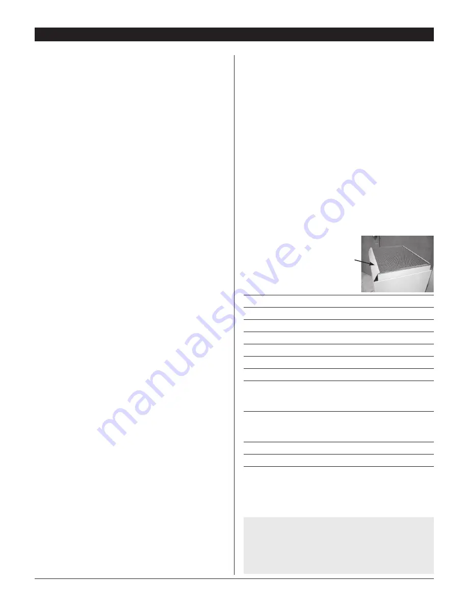
When unpacking, make sure to remove
white protective film off of filter rails.
1. SPeCifiCaTionS
Model:
SD109
Blower:
300 CFM @ 0.0" WG
Power:
742 watts @ 80°F and 60% RH
Supply Voltage:
115 volt – 1 phase - 60 Hz
Current Draw:
6.75 Amps
Energy Factor:
2.88 L/kWh
operating Temp.:
40°F Min., 95°F Max.
Sized for:
2500 Sq. Ft. - Typical
Minimum Performance at 80°f and 60% RH
Water Removal:
109 Pints/Day
Efficiency:
6.09 Pints/kWh
air filter:
MERV-11
Efficiency:
Standard 65% Efficient, ASHRAE Dust Spot Test
Size:
16" x 20" x 2"
Power Cord:
10', – 110-120 VAC, Ground
Drain Hose:
9/16" ID x 8' Direct Gravity Drain Hose
SaniDry XP Dimensions
Unit
With Duct Kit
Shipping
Width:
19 ¾"
22
¾
"
20
¼
"
Height:
36
½
"
43"
43
¼
"
Depth:
17
½
"
17
½
"
22
5
/
8
"
Weight:
106 lbs
122 lbs
TABLE OF CONTENTS
2
SaniDry XP Installer’s & Owner’s Manual
Summary of Contents for SD109 SaniDry XP
Page 1: ......


