This is a publication by Conrad Electronic SE, Klaus-Conrad-Str. 1, D-92240 Hirschau (www.conrad.com).
All rights including translation reserved. Reproduction by any method, e.g. photocopy, microfilming, or the capture in
electronic data processing systems require the prior written approval by the editor. Reprinting, also in part, is prohibited.
This publication represent the technical status at the time of printing.
© Copyright 2016 by Conrad Electronic SE.
1405335_V1_0716_01_VTP_m_en
Installation and connection
Observe the safety instructions!
In every case, the thermostat must be installed such that suitable protection against
contact is present. Otherwise, there is a risk of a life-threatening electric shock!
If in doubt, leave the installation and connection to a specialist.
The installation is determined by the on-site conditions. Among the package contents, you will
find a variety of installation material, e.g., a long retaining bracket.
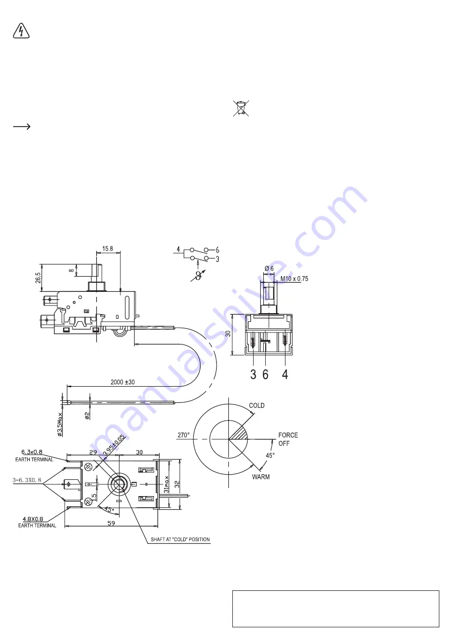
The thermostat is equipped with connections for cable lugs; for this, also observe the overprint
on the underside of the thermostat. Also connect the earth wire to one of the two contacts on
the side (labelled „EARTH TERMINAL“ in the figure below).
For an optimal control by the thermostat, the end of the capillary sensor must be placed with a
length of 150 mm in the area where the temperature is to be measured.
Lay the capillary tube such that it does not lie near heat sources.
Otherwise, the ambient temperature around the capillary tube has a negative effect
on the temperature accuracy of the thermostat.
Operating principle
In the long capillary tube, which is permanently connected to the thermostat, there is a medium
that expands upon warming. At the end of the capillary tube in the thermostat there is a pres-
sure sensor, which is mechanically preloaded by the adjustment spindle.
A consumer activated by the switch contact (such as a cooling compressor) reduces e.g., the
temperature, whereby the medium in the sensor cools and contracts. The control element on
the pressure sensor breaks the circuit when it reaches a given temperature.
The temperature rises again; the medium in the capillary tube expands.
At a given temperature, the circuit closes again and the process is repeated.
The temperature at which the thermostat breaks the circuit can be adjusted using the adjust-
ment spindle.
Since this is not an electronic control, it is not possible to set thermostat exactly to a specific
temperature.
If the adjustment spindle (or the dial installed on it) is turned all the way to the left counter-
clockwise, the thermostat is switched off (at the end of the turning range, you can detect a slight
increase in the amount of force needed or a click; „FORCE OFF“ position; see figure below).
The adjustment range for the temperature control is 270°. The further you turn the dial to the
right (in the „COLD“ direction, see figure below; or „COLDER“ label on the dial), the lower the
temperature that the thermostat attempts to maintain (by turning on the connected cooling unit,
e.g., a cooling compressor).
Disposal
The product must not be disposed of with the household waste. Dispose of an un-
serviceable product in accordance with the relevant statutory regulations.
Technical data
Contact capacity ...............................................250 V/AC, 50/60 Hz, max. 6 A
Contact resistance ............................................< 50 mΩ
Control range ....................................................-34 °C (±2.5 °C) to -9 °C (±1.5 °C)
Max. temperature for thermostat casing ...........+70 °C
Switching hysteresis .........................................-3 °C (±2.5 °C)
Length of the capillary tube ..............................approx. 200 cm (±3 cm)
Bending radius for the capillary tube ................min. 10 mm


