This is a publication by Conrad Electronic SE, Klaus-Conrad-Str. 1, D-92240 Hirschau (www.conrad.com).
All rights including translation reserved. Reproduction by any method, e.g. photocopy, microfilming, or the capture in
electronic data processing systems require the prior written approval by the editor. Reprinting, also in part, is prohibited.
This publication represent the technical status at the time of printing.
© Copyright 2016 by Conrad Electronic SE.
1465105_V1_0916_02_VTP_m_en
c) Handling, operation
• Only use the thermostat when it has been securely mounted.
• Use the product only in a temperate climate, never in a tropical climate.
• Do not use the product if it is damaged. There is a risk of a life-threatening electric
shock!
• If it can be assumed that safe operation is no longer possible, the device must be
turned off and precautions are to be taken to ensure that it is not used unintention-
ally. Do not touch the product.
First switch off the mains voltage to all poles (switch off the connected circuit
breaker or remove the fuse and then switch off the connected RCD).
After this, arrange for a skilled electrician to check the product.
• Safe operation can no longer be assumed if:
- the product shows visible signs of damage
- the product does not work at all or well (flickering light, leaking smoke or a smell
of burning, the light flickers, audible cracking noises, discolouration to the prod-
uct or the adjacent surfaces.)
- the product was stored under unfavourable conditions
Installation and connection
Please observe the chapter „Safety instructions“! If in doubt, leave the installation
and connection to a specialist.
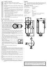
• Pull off the rotary knob. Then, remove the cover by unscrewing the large plastic screw in the
middle of the front (rotate to the left in counter-clockwise direction).
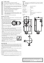
• Mount the thermostat at the desired point of
the radiator pipe. A special metal fastener
strap is included for this. The thermostat can
be fastened with the fastener strap and the
two hooks on the left and right of the ther-
mostat.
• When laying out the capillary pipe, make
sure that it is not bent or otherwise dam-
aged.
• To achieve an optimal heat conduction, heat conductive paste may have to be applied be-
tween sensor and radiator pipe. Do not damage the image sensor!
• The thermostat has 4 screw terminals. Remove the outer insulation of the power supply
cable and then remove the insulation of the individual lines over a distance of approx. 5 mm.
• Loosen the nut of the cable connection and slide the power supply cable through the cable
connection.
• Fasten the power supply cable with the cable connection so that the outer insulation of the
power supply cable is securely fixed in the cable connection. This acts as strain relief.
• Connect the power supply cable to the corresponding screw terminals.
• Connect the protective earth (PE, green-yellow cable) to the metal housing of the thermostat
with the screw terminal.
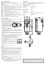
• The other screw terminals must be selected and connected corre-
sponding to the external allocation of the thermostat.
If the measured temperature exceeds the set switch values, the switch
contact changes from position „C-1“ to position „C-2“.
• Replace the cover and secure it with the plastic screw that you re-
moved earlier.
• Place the rotary knob back in place, note the correct orientation.
Operating principle
In the long capillary tube (and the sensor tip), which is permanently connected to the thermo-
stat, there is a liquid that expands upon warming. At the end of the capillary tube in the ther-
mostat there is a pressure sensor, which is mechanically preloaded by the adjustment spindle.
A heating device, which is activated via the switch contact, increases the temperature; the liquid
in the installed sensor warms up and expands.
The control element on the pressure sensor breaks the circuit when it reaches a given tem-
perature.
The temperature falls again and the liquid in the capillary tube contracts.
At a given temperature, the circuit closes again and the process is repeated.
The temperature at which the thermostat breaks the circuit can be adjusted using the adjust-
ment spindle.
Since this is not an electronic control, it is not possible to set thermostat exactly to a specific
temperature.
The switch contact allows control of both cooling and heating, depending which
thermostat contacts are used to make the connection (C + 1 or C + 2).
Disposal
Electronic devices are recyclable material and do not belong in the household
waste. Dispose of an unserviceable product in accordance with the relevant statu-
tory regulations.
Technical data
Operating voltage ......................... 220 - 250 V/AC, 50/60 Hz
Switch current ............................... 16 A (ohmic)
......................................................
4 A (inductive)
Protection class ............................ I
Protection grade ........................... IP40
Control range ................................ 0 °C to +90 °C
Switching hysteresis ..................... 5 ±3 °C
Ambient conditions ....................... Temperature 0 °C to +90 °C, air humidity 10% to 90%
relative, not condensing
Dimensions ................................... see illustration
Weight .......................................... 123 g

