27
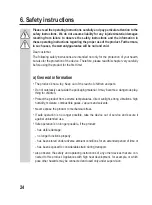
Be careful not to short-circuit the input and output lines. Keep the wires separate.
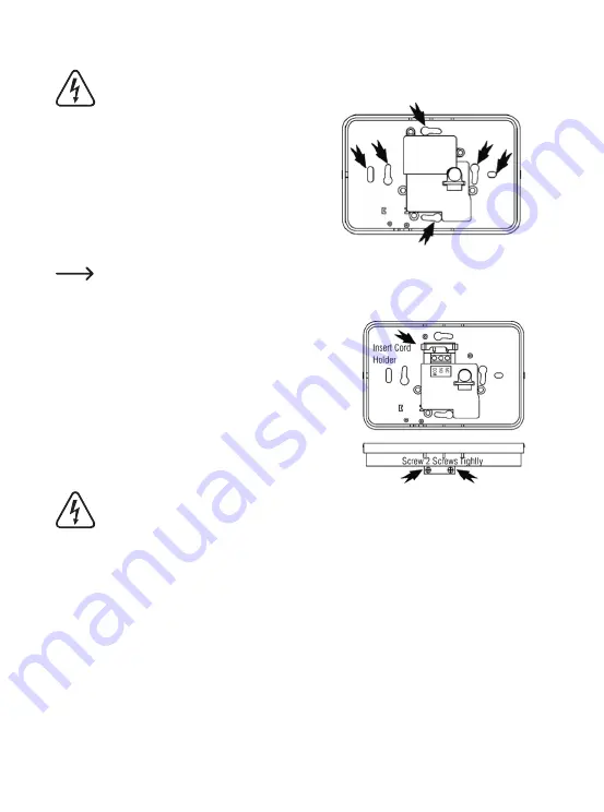
• Use the device as a template and mark the locations for
the borehole on the wall. To do this use the mounting
holes in the rear panel suitable for your mounting posi-
tion. The holes chosen should be located opposite each
other to ensure maximum stability.
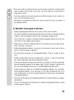
• Use a 6 mm drill and bore at least 30 mm deep at the marks.
Note that, depending on the substrate, other fastening material than the material in the
installation kit .enclosed may be required. Use the type of installation depending on the
conditions.
• Press the anchors in until they fully disappear into the wall.
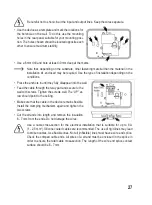
• Feed the cable through the relay part and secure to the
wall with screws. Tighten the screws well. The “UP” ar-
row should point to the ceiling.
• Make sure that the cable in the device remains flexible.
Install the clamping mechanism again and tighten the
two screws.
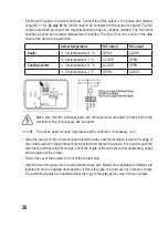
• Cut the strands into length and remove the insulation
6 - 7 mm from the ends. Do not damage the wires.
Use a cable cross-section for the electrical installation that is suitable for up to 8 A
(1 - 2.5 mm
2
). Silicone coated cables are recommended. The use of rigid lines may lead
to broken cables. Use flexible lines. Not all (inflexible) lines must have a wire end splice.
Check the crimped cable ends. All wires of a strand must be enclosed in the splice in
order to ensure the total cable cross-section. The length of the wire end splice contact
surface should be 6 - 7 mm.


