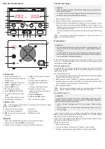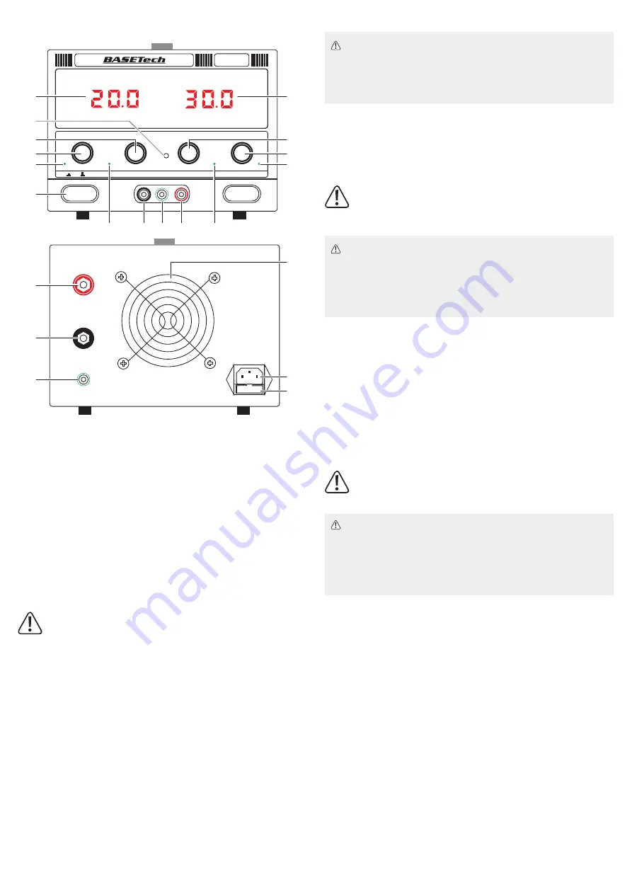
Operating elements
.
+
_
GND
FUSE
A
V
CURRENT
VOLTAGE
O.T.
FINE
C.C
OFF
COARSE
O.V. SET
C.V.
GND
ON
COARSE
O.V.
FINE
_
+
POWER
BT-3020
1
3
4
6
16
17
18
8
9
10
12
13
14
19
20
21
5
15
7
11
2
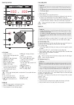
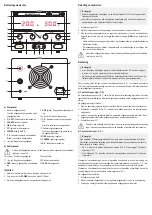
a) Front panel
1 Output current indicator
Shows the output current measured at the
output terminals
2
O.V. SET:
Over voltage potentiometer
3
COARSE
(current) regulator
4
FINE
(current) regulator
5
OT:
Over temperature indicator
6
POWER
(ON/OFF) button
7
C.C.:
Constant current mode indicator
Lights up in constant current mode
8
-
(black): Negative output terminal
9
GND
(green): Chassis ground output
terminal
10
+
(red): Positive output terminal
11
C.V.:
Constant Voltage mode indicator.
Lights up in constant voltage mode
12 Output voltage indicator
Shows the output voltage measured at the
output terminals
13
FINE
(voltage) regulator
14
COARSE
(voltage) regulator
15
O.V.:
Over voltage indicator
b) Back panel
Use the output terminals located on the back panel if the connected load current
exceeds 10 A.
16
+
(red): Positive output terminal
17
-
(black): Negative output terminal
18
GND
(green): Chassis ground output
terminal
19 Air outlet
20 Power supply socket
21
FUSE:
Fuse holder
Setting up
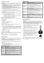
1. Place the lab power supply on an sturdy and even surface.
2. Make sure the
POWER
button is in the OFF position.
3. Connect the power cord to a suitable power supply.
Connecting loads
Important
• Switch connected loads and the lab power supply OFF before disconnecting and con-
necting.
• The total power of all connected loads should not exceed the maximum power output
of the lab power supply.
1. Switch the power OFF.
2. Set the voltage and current supply dials to minimum.
3. Connect the positive output terminal (
+
) and negative output terminal (
-
) with a load or simi-
lar component. Use the dedicated ground connection (
GND
) to earth the load.
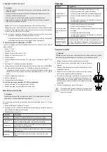
- Use adequately dimensioned cables with 4 mm banana plugs or standardized lab cables.
- The socket heads can be screwed on to attach cable strands using screw terminals.
If the connected load current exceeds 10 A, use the output terminals located on the
back panel.
Operation
Important
• If running inductive loads e.g. magnetic coils, DC motors, stepper motors etc., adjust
the voltage and current slowly.
• The maximum uninterrupted operating time of the lab power supply is 24 hours. After
that the lab power supply should be switched off until it has cooled down to ambient
temperature.
This power supply operates as a constant voltage (C.V.) or constant current (C.V.) source.
Automatic crossover to either mode of operation occurs when the load condition changes.
a) Constant voltage (C.V.)
The constant voltage source (C.V.) will be active if the load current is less than the preset cur-
rent limit value. Use the voltage regulator controls the set the output voltage.
To set the output voltage:
1. Turn the voltage regulators anti-clockwise to minimum and the current regulators clockwise
to maximum.
2. Switch the power ON. The C.V. indicator will light in constant voltage mode.
3. Slowly increase the voltage until you reach the desired output voltage. The output voltage
indicator will show the output voltage at the terminals.
4. Switch the power OFF.
Before connecting a load, make sure the set voltage is less than the rated voltage of
the load or electronic components.
b) Constant current (C.C.)
Important
Read section “d) Connecting loads” before attempting to set any current limits. You have
to switch on a connected load and the lab power supply to be able to set the exact current
limit.
•
The C.V. must first be set before setting the C.C. See section “Constant voltage (C.V.)”
• During C.C setting, do not rotate the voltage dial when the C.V value has been set.
When the load current is ≥ preset current limit, the power supply will cross over to constant cur
-
rent mode. The voltage will drop, the “C.C.” mode indicator will light up, and the power supply
will operate as a constant current source.
When the load current drops below the preset current limit, the supply will return to constant
voltage (C.V.) mode.
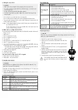
Setting the output current:
1. Switch the power ON.
2. Connect the positive output terminal (
+
) and negative output terminal (
-
) with a load.
3. Slowly increase the current until you reach the desired output current.


