background image


22


9.  Maintenance 


If the Mux is mounted in a cabinet, door should remain closed as often as possible. A lock 
should be used if necessary. 


The ambient temperature of the Mux should be checked in the operating environment at its 
highest temperature. The temperature should not exceed 70ºC. Doing so will not damage the 
electronics but may affect the temperature measurement accuracy. If the temperature exceeds 
80ºC, failure is possible. Use radiation shielding or the optional purge air to keep the 
electronics cool.   


Periodically check Mux for signs of deposition of water, oil, dirt, etc. If necessary, clean it by 
disconnecting the DC power and wiping it down with a soft, slightly damp cloth. 


If the Mux is mounted in a cabinet, check the inside of the cabinet for dirt, oil, water, etc. If 
discovered, take appropriate action to prevent damage to the electronic components. 


Summary of Contents for EXACTUS IFM8-I

Page 1: ...weights etc given herein may change without prior information and do not constitute the agreed contractual quality of the product It is the responsibility of the recipient of our products to ensure th...

Page 2: ...ault Parameters 4 Configuration Communication 5 Configuration Menu 6 Alarm Configuration 7 Analog Output Wiring 8 Mounting 9 Maintenance 10 Warnings Appendix 1 MODBUS TCP Implementation 1 Product Over...

Page 3: ...2 Figure 1 1 IFM8 IA Balloon View Note Pyrometer channel numbering sequence varies on some hardware configurations...

Page 4: ...3 Figure 1 2 IFM8 IA Overview...

Page 5: ...tts 600mA 24VDC Pin Assignments Pin 1 V Pin 2 V circuit ground Pin 3 earth chassis ground Terminal Type Removable 3 pin 5 00 5 08mm plug NOTE Relay drive current 17mA for each relay is not factored in...

Page 6: ...d Ethernet Ports 23 Telnet Port for configuration 502 Modbus TCP Port 6789 Mux Server Port 6790 UDP Announcement Port Pyrometer Ports Number of input Ports channels 8 Connectors RJ 45 Pin Assignments...

Page 7: ...utput Ripple 0 003 of Full Scale Reverse Polarity Protection Yes up to 85V Over Current Protection Yes limited to 40mA Maximum Voltage At Output Pins 48VDC 24VDC recommended Minimum Voltage At Output...

Page 8: ...imits are exceeded Pyrometers will remain powered down until power to the Industrial Mux is cycled off and back on The Pyrometer Supply Voltage is set to 6200mV adequate for standard pyrometer power c...

Page 9: ...e of any LAN type 2 Set the IP address of the PC a Right click on My Network Places and choose Properties from the pop up menu See Figure 4 1 Figure 4 1 Selecting Properties of My Network Places b Dou...

Page 10: ...9 c The following screen Figure 4 3 will appear Click the Properties button Figure 4 3...

Page 11: ...10 d Double click the Internet Protocol TCP IP line Figure 4 4 this will bring up the screen shown in Figure 4 5 Figure 4 4 Figure 4 5...

Page 12: ...not be the last number of the Industrial Mux e g if the Default Address is used this would be 80 iii The last number of the Default Gateway must be 1 iv The Subnet Mast must be 255 255 255 0 as shown...

Page 13: ...the TCP IP Winsock option from the Connect using drop down box then enter the Mux s IP address and click OK See Figure 4 8 Figure 4 8 d When you hit the OK buttons you should get the menu shown in Fi...

Page 14: ...ustrial Mux f HyperTerminal may not automatically display user keystrokes to the screen To turn on the echo feature press the Properties button circled in red in Figure 4 10 below and select the Setti...

Page 15: ...14 Figure 4 10 Check the Echo typed characters locally check box and close the dialog windows Figure 4 11...

Page 16: ...d remain at default value of 6200mv Mode Options Used to configure the alarms for individual pyrometers More detail is provided in Alarm Configuration section Mux Ambient Alarm Configuration Brings up...

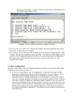
Page 17: ...Menu See Figure 4 9 will bring up the Alarm configuration menu shown in Figure 6 1 Pyrometer Internal Temperature Selecting Option 3 brings up the Pyrometer Internal Temperature configuration setup sc...

Page 18: ...17 Figure 6 1 Alarm configuration menu Figure 6 2 Pyrometer Internal Temperature Alarm Configuration Menu...

Page 19: ...d to do so energize one of the relays When the Pyrometer Analog Watchdog Item 4 in Figure 6 1 is enabled then item 5 Pyrometer Watchdog Actions should be configured This offering has a self explanator...

Page 20: ...xternally Many data logging systems are configured to supply this voltage if yours is not you can use the same power supply driving the Industrial Mux to provide the power This is outlined in the sche...

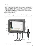
Page 21: ...ount top tabs and pull the instrument away for the rail It is recommended that the Mux be mounted in a cabinet or NEMA enclosure rated for area of use See mounting examples in section 8 1 8 1 Electron...

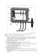
Page 22: ...Cooling Air Inlet Valve D Covered Punch out holes for Power Input and Signal Output Cables E Pyrometer Channel Expansion Locations F Conduit Contains either the fiber optic transmission or power data...

Page 23: ...may affect the temperature measurement accuracy If the temperature exceeds 80 C failure is possible Use radiation shielding or the optional purge air to keep the electronics cool Periodically check M...

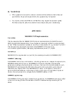
Page 24: ...aging_Implementation_Guide_V1_0b pdf TCP IP Port MODBUS TCP is implemented over port 502 the standard port number for MODBUS TCP MODBUS Addressing Each MODBUS device has an 8 bit address All of the py...

Reviews: