4-1
!"#$%&'()
INSTALLATION
GENERAL
When not shipped as part of a control or switchgear panel, the relays are shipped in sturdy cartons to
prevent damage during transit. Immediately upon receipt of a relay, check the model and style number
against the requisition and packing list to see that they agree. Visually inspect the relay for damage that may
have occurred during shipment. If there is evidence of damage, immediately file a claim with the carrier and
notify the Regional Sales Office, or contact the Sales Representative at Basler Electric, Highland, Illinois.
In the event the relay is not to be installed immediately, store the relay in its original shipping carton in a
moisture and dust free environment. When relay is to be placed in service, it is recommended that the
operational test procedure (Section 5) be performed prior to installation.
RELAY OPERATING PRECAUTIONS
Before installation or operation of the relay, note the following precautions:
1. A minimum of 0.2 A in the output circuit is required to ensure operation of current operated targets.
2. Do not touch target indicator vanes. Always reset targets by use of the target reset lever.
3. The relay is a solid-state device. If a wiring insulation test is required, remove the connecting plugs
and withdraw the cradle from its case.
4. When the connecting plugs are removed the relay is disconnected from the operating circuit and will
not provide system protection. Always be sure that external operating (monitored) conditions are
stable before removing a relay for inspection, test, or service.
5. Be sure the relay case is hard wired to earth ground using the ground terminal on the rear of the
unit. It is recommended to use a separate ground lead to the ground bus for each relay.
DIELECTRIC TEST
In accordance with IEC 255-5 and ANSI/IEEE C37.90-1978, one-minute dielectric (high potential) tests may
be performed using up to 1500 Vac (45-65 hertz). This device employs decoupling capacitors to ground
from the following terminals: power supply, voltage sensing input, and output contacts. At 1500 Vac, a
leakage current of up to 40 milliamperes per terminal is to be expected. Because of the high leakage
current, it is recommended that dielectric tests be performed using dc voltages equivalent to the peak ac
value (2,120 Vdc).
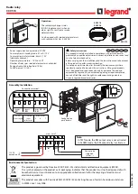
!"#$%&$'
Because the relay is of solid state design, it does not have to be mounted vertically. Any convenient
mounting angle may be chosen. Relay outline dimensions and panel drilling diagrams are supplied at the
end of this section.
("$$)(%&"$*
Incorrect wiring may result in damage to the relay. Except for the ground wire (see following note),
connections should be made with minimum wire size of 14 AWG. Typical external connections are shown
in Figures 4-1 through 4-8. Internal connections are shown in Figures 4-10 through 4-15.
Summary of Contents for BE-51/27C
Page 1: ...0 1 2 3 4 5 67869 ABC DEF G 6H II GGJ KL M DEF DEK...
Page 16: ...BE1 51 27C Controls and Indicators 2 2 Figure 2 1 Location of Controls and Indicators...
Page 20: ...BE1 51 27C Controls and Indicators 2 6...
Page 22: ...BE1 51 27C Functional Description 3 2 Figure 3 2 Functional Block Diagram...
Page 32: ...BE1 51 27C Installation 4 7 Figure 4 10 Typical Internal Diagram Sensing Input Type L...