BE1-51/27C Installation
4-2
NOTE
Be sure the relay case is hard-wired to earth ground with no smaller than 12 AWG
copper wire attached to the ground terminal on the rear of the relay case. When the
relay is configured in a system with other protective devices, it is recommended to use
a separate lead to the ground bus from each relay.
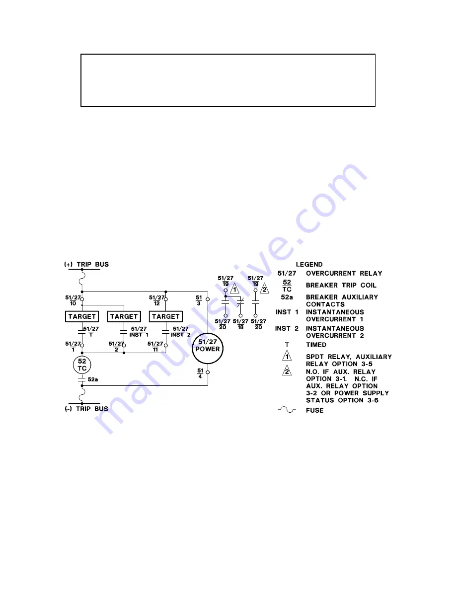
To prevent an inductive overload of the relay contacts, it is necessary to break the trip circuit externally
through the 52a contacts.
Relay circuitry is connected to the case terminals by removable connection plugs (1 plug for 10-terminal
cases and 2 plugs for 20-terminal cases). Removal of the connection plug(s) opens the N.O. trip contact
circuits and shorts the N.C. trip contact circuits before opening the power and Sensing Circuits.
Figure 4-1. Typical External Connections, Current Operated Targets, DC Powered
Summary of Contents for BE-51/27C
Page 1: ...0 1 2 3 4 5 67869 ABC DEF G 6H II GGJ KL M DEF DEK...
Page 16: ...BE1 51 27C Controls and Indicators 2 2 Figure 2 1 Location of Controls and Indicators...
Page 20: ...BE1 51 27C Controls and Indicators 2 6...
Page 22: ...BE1 51 27C Functional Description 3 2 Figure 3 2 Functional Block Diagram...
Page 32: ...BE1 51 27C Installation 4 7 Figure 4 10 Typical Internal Diagram Sensing Input Type L...