


BE1-51/27C Tests and Adjustments
5-2
(c) Sensing Input Type T (Three-Phase with Neutral Sensing). Refer to Figure 5-3. Ensure that
the timed output terminals 1 and 10 are connected. Also, verify that either A, B, or C current
sense terminals are connected initially (N terminals will be connected later in the test).
(d) Sensing Input Type A (Three-Phase Sensing). Refer to Figure 5-4. Ensure that the timed
output terminals 1 and 10 are connected. Also, verify that either A, B, or C current sense
terminals are connected initially (N terminals will be connected later in the test). Ensure that
the voltage sense terminals and the current sense terminals are connected to the same phase.
(e) Sensing Input Type D (Three-Phase with Neutral Sensing). Refer to Figure 5-5. Ensure that
the timed output terminals 1 and 10 are connected. Also, verify that either A, B, or current
sense terminals are connected initially (N terminals will be connected later in the test).
(f) Sensing Input Type J (Two-Phase with Neutral Sensing). Refer to Figure 5-6. Ensure that the
timed output terminals 1 and 10 are connected. Also, verify that either A, B, or C current sense
terminals are connected initially (N terminals will be connected later in the test).
Step 2. Remove the relay front cover.
Step 3. Set the front panel
TIME DIAL
selector and, if present, the front panel
TIME DIAL (NEUTRAL)
selector to 99.
Step 4. Adjust the front panel
INST 1
and
INST 2
controls, if present, fully clockwise (CW).
Step 5. Adjust front panel
TAP CAL
control, and if present, front panel
TAP (NEUTRAL)
control fully CW.
Step 6. Ensure that the relay front panel
TARGETS
, if present, are reset.
Step 7. Apply 100% of nominal voltage based on the sensing input type for your relay.
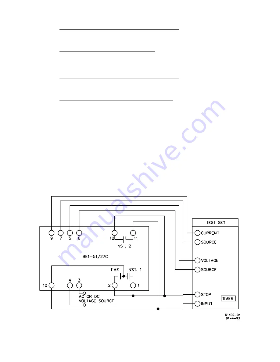
Figure 5-1. Test Setup for Sensing Input Type L (Single-Phase Sensing)
Summary of Contents for BE-51/27C
Page 1: ...0 1 2 3 4 5 67869 ABC DEF G 6H II GGJ KL M DEF DEK...
Page 16: ...BE1 51 27C Controls and Indicators 2 2 Figure 2 1 Location of Controls and Indicators...
Page 20: ...BE1 51 27C Controls and Indicators 2 6...
Page 22: ...BE1 51 27C Functional Description 3 2 Figure 3 2 Functional Block Diagram...
Page 32: ...BE1 51 27C Installation 4 7 Figure 4 10 Typical Internal Diagram Sensing Input Type L...


