


BE1-51/27C Tests and Adjustments
5-5
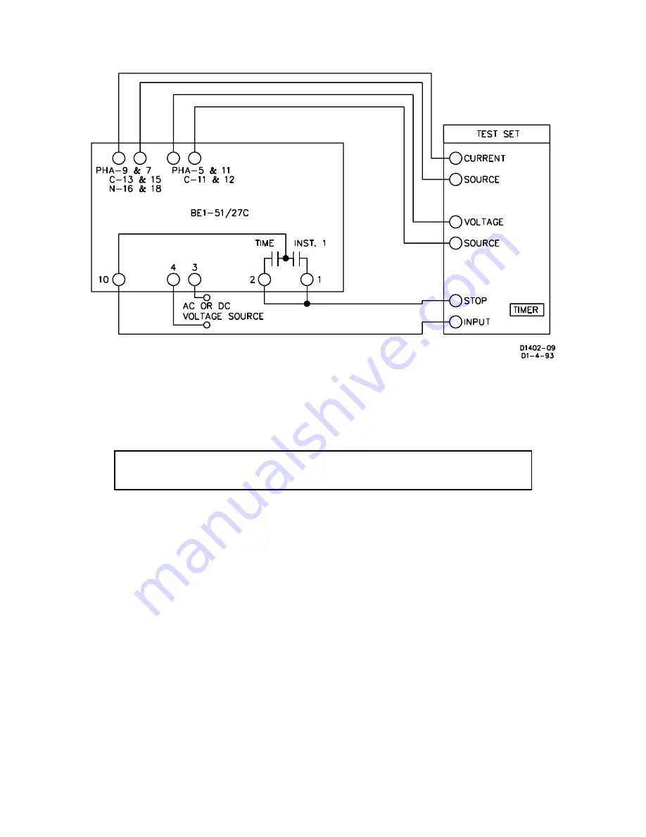
NOTE
During this test, disregard any indication on the test setup timer.
Figure 5-6. Test Setup for Sensing Input Type J (Two-Phase with Neutral Sensing)
Time Overcurrent Pickup Test
This test will check the minimum and maximum overcurrent pickup points of the time overcurrent element.
Step 1. Perform the Preliminary Instructions.
Step 2. Set the front panel
TAP
selector to
A
.
Step 3. Adjust the test set, for an overcurrent threshold having one of the following values:
a) 0.5 A for relays with Sensing Input Range 1, 2, or 4.
b) 1.5 A for relays with Sensing Input Range 3 or 5.
Step 4. Slowly adjust the front panel
TAP CAL
Control CCW until the front panel
TIMING
Indicator
illuminates.
RESULT:
For the phase minimum overcurrent pickup point of 0.5 A (Step 3a., above) or 1.5 A
(Step 3b., above) the front panel
TAP CAL
control should be near its maximum CCW limit.
Step 5. Adjust the front panel
TAP CAL
control fully CW to allow measurement of the actual overcurrent
pickup point at the
A
setting of the front panel
TAP
selector. Note that the front panel
TIMING
Indicator will extinguish. Do not disturb this setting.
Summary of Contents for BE-51/27C
Page 1: ...0 1 2 3 4 5 67869 ABC DEF G 6H II GGJ KL M DEF DEK...
Page 16: ...BE1 51 27C Controls and Indicators 2 2 Figure 2 1 Location of Controls and Indicators...
Page 20: ...BE1 51 27C Controls and Indicators 2 6...
Page 22: ...BE1 51 27C Functional Description 3 2 Figure 3 2 Functional Block Diagram...
Page 32: ...BE1 51 27C Installation 4 7 Figure 4 10 Typical Internal Diagram Sensing Input Type L...


