9424200996
1-1
BE1-11
m
Introduction
1 • Introduction
The BE1-11
m
Motor Protection System provides flexible, reliable, and economical protection, control,
monitoring, and measurement functions for medium and large motors. The BE1-11
m
offers thermal
protection of the motor with a current-based thermal model that includes unbalanced current biasing,
custom voltage dependent curves, RTD biasing, and emergency start override. The system offers
differential and overcurrent protection for internal faults as well as overcurrent, voltage, frequency, and
power elements for protection against abnormal system and process conditions. The BE1-11
m
offers
motor maintenance data, learns and records start data, breaker- and trip-circuit monitoring, oscillography,
and sequential events recording. Control features include manual and emergency starting, thermal
capacity start inhibiting, start and stop buttons, virtual selector switches, virtual lockout, and variable-
mode timers. System metering and status information are available at the BE1-11
m
front panel and
through the BE1-11
m
communication ports. The capabilities of the BE1-11
m
make it appropriate for use in
medium and large motor applications and in critical small motor applications. BE1-11
m
applications
include utility power generation facilities, water treatment facilities, petroleum drilling and refining, pulp
and paper mills, and chemical plants.
A front-panel USB port or optional rear Ethernet port enables local communication between the BE1-11
m
and a PC operating with BESTCOMS
Plus
®
software. BESTCOMS
Plus
software simplifies the
commissioning process by providing a graphical interface for setting the BE1-11
m
and configuring a
protection and control scheme for your application. Through BESTCOMS
Plus
, all BE1-11
m
settings and
logic can be retained in a file for printing or uploading to other BE1-11
m
protection systems. Oscillography
and sequential events records can be retrieved from a BE1-11
m
, viewed, and printed.
Front panel features include a large, backlit alphanumeric display and LED indicators that display system
parameters, BE1-11
m
settings, and BE1-11
m
status. Pushbuttons enable navigation through the display
menu, changes to settings, and resetting of targets (with password access).
Applications
The capabilities of the BE1-11
m
make it ideally suited for applications with the following attributes:
•
Applications with large motor or important process that require comprehensive motor protection
and control
•
Applications that require loss of excitation protection for synchronous motors
•
Applications requiring an interface between the protection and control package and the process
control systems
•
Isolation between the RTDs and the BE1-11
m
due to distance between the BE1-11
m
package
and the RTD module
•
Low burden to extend the linear range of CTs
•
The flexibility provided by wide setting ranges, multiple setting groups, and multiple coordination
curves in one unit
•
The economy and space savings provided by a multifunction, multiphase unit. This one unit can
provide all of the protection, control, metering, and local and remote indication functions required
for typical applications.
•
High-speed Ethernet communications and protocol support
•
The capabilities of a numeric multifunction relay
•
The small size and limited behind-panel projection facilitates modernizing protection and control
systems in existing equipment
•
Detection of low ground current levels (SEF option)
•
IEC 61850 functionality
Summary of Contents for BE1-11m
Page 8: ...vi 9424200996 Revision History BE1 11m...
Page 12: ...x 9424200996 Contents BE1 11m...
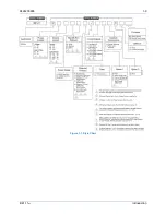
Page 21: ...9424200996 1 9 BE1 11m Introduction Figure 1 1 Style Chart...
Page 22: ...1 10 9424200996 Introduction BE1 11m...
Page 40: ...3 6 9424200996 Controls and Indicators BE1 11m Figure 3 3 Front Panel Display Setup Screen...
Page 54: ...5 6 9424200996 Phase Undervoltage 27P Protection BE1 11m...
Page 56: ...6 2 9424200996 Negative Sequence Voltage 47 Protection BE1 11m...
Page 61: ...9424200996 7 5 BE1 11m Phase Overvoltage 59P Protection Figure 7 3 Overvoltage Settings Screen...
Page 62: ...7 6 9424200996 Phase Overvoltage 59P Protection BE1 11m...
Page 68: ...8 6 9424200996 Auxiliary Overvoltage 59X Protection BE1 11m...
Page 80: ...12 4 9424200996 Instantaneous Overcurrent 50 Protection BE1 11m...
Page 84: ...13 4 9424200996 Breaker Failure 50BF Protection BE1 11m...
Page 92: ...14 8 9424200996 Inverse Overcurrent 51 Protection BE1 11m...
Page 105: ...9424200996 18 3 BE1 11m Power Factor 55 Protection Figure 18 2 Power Factor Settings Screen...
Page 106: ...18 4 9424200996 Power Factor 55 Protection BE1 11m...
Page 110: ...19 4 9424200996 Resistance Temperature Detector 49RTD Protection BE1 11m...
Page 118: ...20 8 9424200996 Thermal Curve 49TC Protection BE1 11m...
Page 122: ...22 2 9424200996 Starts per Time Interval 66 Protection BE1 11m...
Page 124: ...23 2 9424200996 Restart Inhibit Protection BE1 11m...
Page 140: ...28 4 9424200996 Breaker Control Switch 101 BE1 11m...
Page 148: ...29 8 9424200996 Setting Groups BE1 11m...
Page 156: ...30 8 9424200996 Metering BE1 11m Figure 30 11 RTD Meter Screen...
Page 158: ...31 2 9424200996 Digital Points BE1 11m Figure 31 2 Digital Points Monitor Screen...
Page 177: ...9424200996 34 5 BE1 11m Motor Reporting Figure 34 9 Learned Motor Data Screen...
Page 178: ...34 6 9424200996 Motor Reporting BE1 11m...
Page 184: ...35 6 9424200996 Alarms BE1 11m...
Page 186: ...36 2 9424200996 Differential Reporting BE1 11m...
Page 196: ...38 4 9424200996 Demands BE1 11m...
Page 198: ...39 2 9424200996 Load Profile BE1 11m...
Page 208: ...41 6 9424200996 Trip Circuit Monitor 52TCM BE1 11m...
Page 212: ...42 4 9424200996 Fuse Loss 60FL BE1 11m...
Page 218: ...43 6 9424200996 BESTnet Plus BE1 11m Figure 43 8 Power Quality Page...
Page 221: ...9424200996 44 3 BE1 11m Mounting Figure 44 3 Case Side Dimensions...
Page 235: ...9424200996 45 5 BE1 11m Terminals and Connectors Figure 45 7 Example of Reversed CT Polarity...
Page 236: ...45 6 9424200996 Terminals and Connectors BE1 11m...
Page 269: ...9424200996 48 15 BE1 11m BESTlogic Plus Figure 48 4 Logic Page 1 for Default Logic...
Page 288: ...49 10 9424200996 Communication BE1 11m Figure 49 14 Modbus Mapping Screen...
Page 306: ...52 4 9424200996 Device Information BE1 11m...
Page 314: ...53 8 9424200996 Configuration BE1 11m Figure 53 3 Display Units Screen...
Page 318: ...54 4 9424200996 Introduction to Testing BE1 11m...
Page 330: ...56 6 9424200996 Commissioning Testing BE1 11m...
Page 336: ...58 4 9424200996 Phase Undervoltage 27P Test BE1 11m...
Page 340: ...59 4 9424200996 Phase Overvoltage 59P Test BE1 11m...
Page 352: ...60 12 9424200996 Auxiliary Overvoltage 59X Test BE1 11m...
Page 360: ...61 8 9424200996 Frequency 81 Test BE1 11m...
Page 364: ...62 4 9424200996 Instantaneous Undercurrent 37 Test BE1 11m...
Page 376: ...63 12 9424200996 Instantaneous Overcurrent 50 Test BE1 11m...
Page 396: ...65 16 9424200996 Inverse Overcurrent 51 Test BE1 11m...
Page 408: ...67 6 9424200996 Power 32 Test BE1 11m...
Page 412: ...68 4 9424200996 Loss of Excitation Reverse Var Based 40Q Test BE1 11m...
Page 426: ...70 10 9424200996 Thermal Curve 49TC Test BE1 11m...
Page 432: ...72 4 9424200996 Starts per Time Interval 66 Test BE1 11m...
Page 436: ...73 4 9424200996 Restart Inhibit Test BE1 11m...
Page 440: ...74 4 9424200996 Virtual Control Switches 43 Test BE1 11m...
Page 450: ...75 10 9424200996 Logic Timers 62 Test BE1 11m...
Page 464: ...79 8 9424200996 Troubleshooting BE1 11m...
Page 480: ...80 16 9424200996 Specifications BE1 11m...
Page 600: ...84 56 9424200996 Settings Calculation Examples BE1 11m Figure 84 70 Logic Page 4 Part 1...
Page 602: ...84 58 9424200996 Settings Calculation Examples BE1 11m...
Page 608: ...85 6 9424200996 BESTCOMSPlus Settings Loader Tool BE1 11m...
Page 609: ......


