9424200996
1-3
BE1-11
m
Introduction
IRIG
A standard unmodulated IRIG-B input receives time synchronization signals from a master clock.
Automatic daylight saving time compensation can be enabled and set for floating or fixed dates.
NTP (Network Time Protocol)
NTP synchronizes the real-time clock to network time servers through the Ethernet port. BESTCOMS
Plus
is used to establish the priority of time reference sources available to the BE1-11
m
, IRIG-B, NTP, DNP,
and RTC (real-time clock). The NTP address is set using BESTCOMS
Plus
.
Communications
Three independent communication ports provide access to all BE1-11
m
functions. A USB (universal serial
bus) port is located on the front panel, a two-wire RS-485 port is located on the rear panel, and an
optional Ethernet port is located on the rear panel. The RS-485 and Ethernet ports are electrically
isolated.
Modbus
®
and DNP3 protocols are optionally available for the RS-485 or Ethernet communication port.
The IEC 61850 protocol is optionally available for the Ethernet port when RS-485 option is N (None).
Separate instruction manuals cover each available protocol. Consult the product bulletin or Basler Electric
for availability of these options and instruction manuals. Modbus sessions can be operated
simultaneously over the Ethernet and RS-485 ports.
System Parameters
Three-phase currents and voltages are digitally sampled and the fundamental is extracted using a
Discrete Fourier Transform (DFT) algorithm.
The voltage sensing circuits can be configured for single-phase, three-phase-three-wire, or four-wire
voltage transformer circuits. Voltage sensing circuitry provides voltage protection, frequency protection,
polarizing, and watt/var metering. Neutral-shift, positive-sequence, and negative-sequence voltage
magnitudes are derived from the three-phase voltages. Digital sampling of the measured frequency
provides high accuracy at off-nominal values.
An auxiliary voltage sensing input (Vx) provides protection capabilities for over/undervoltage monitoring of
the fundamental and third harmonic voltage of the VT source connected to the Vx input. This capability is
useful for ground fault protection.
Each current sensing circuit has low burden and is isolated. Neutral, positive-sequence, and negative-
sequence current magnitudes are derived from the three-phase currents. An independent ground current
input is available for direct measurement of the current in a transformer neutral, tertiary winding or flux
balancing current transformer. Either one or two sets of CTs are provided in the BE1-11
m
depending on
the style number. Refer to the style chart for more information.
Programmable Inputs and Outputs
Programmable inputs and outputs are described in the following paragraphs.
Programmable Inputs
Either seven or 10 programmable contact sensing inputs with programmable signal conditioning provide a
binary logic interface to the protection and control system. Refer to the style chart for I/O options. Each
input function and label is programmable using BESTlogic
Plus
. A user-meaningful label can be assigned
to each input and to each state (energized and de-energized) for use in reporting functions. Board
mounted jumpers support dual voltage ratings.
Programmable Outputs
Either eight or five programmable general-purpose contact outputs provide a binary logic interface to the
protection and control system. Refer to the style chart for I/O options. One programmable, failsafe contact
output serves as an alarm output. Each output function and label is programmable using BESTlogic
Plus
.
A user-meaningful name can be assigned to each output and to each state (energized and de-energized)
Summary of Contents for BE1-11m
Page 8: ...vi 9424200996 Revision History BE1 11m...
Page 12: ...x 9424200996 Contents BE1 11m...
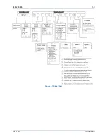
Page 21: ...9424200996 1 9 BE1 11m Introduction Figure 1 1 Style Chart...
Page 22: ...1 10 9424200996 Introduction BE1 11m...
Page 40: ...3 6 9424200996 Controls and Indicators BE1 11m Figure 3 3 Front Panel Display Setup Screen...
Page 54: ...5 6 9424200996 Phase Undervoltage 27P Protection BE1 11m...
Page 56: ...6 2 9424200996 Negative Sequence Voltage 47 Protection BE1 11m...
Page 61: ...9424200996 7 5 BE1 11m Phase Overvoltage 59P Protection Figure 7 3 Overvoltage Settings Screen...
Page 62: ...7 6 9424200996 Phase Overvoltage 59P Protection BE1 11m...
Page 68: ...8 6 9424200996 Auxiliary Overvoltage 59X Protection BE1 11m...
Page 80: ...12 4 9424200996 Instantaneous Overcurrent 50 Protection BE1 11m...
Page 84: ...13 4 9424200996 Breaker Failure 50BF Protection BE1 11m...
Page 92: ...14 8 9424200996 Inverse Overcurrent 51 Protection BE1 11m...
Page 105: ...9424200996 18 3 BE1 11m Power Factor 55 Protection Figure 18 2 Power Factor Settings Screen...
Page 106: ...18 4 9424200996 Power Factor 55 Protection BE1 11m...
Page 110: ...19 4 9424200996 Resistance Temperature Detector 49RTD Protection BE1 11m...
Page 118: ...20 8 9424200996 Thermal Curve 49TC Protection BE1 11m...
Page 122: ...22 2 9424200996 Starts per Time Interval 66 Protection BE1 11m...
Page 124: ...23 2 9424200996 Restart Inhibit Protection BE1 11m...
Page 140: ...28 4 9424200996 Breaker Control Switch 101 BE1 11m...
Page 148: ...29 8 9424200996 Setting Groups BE1 11m...
Page 156: ...30 8 9424200996 Metering BE1 11m Figure 30 11 RTD Meter Screen...
Page 158: ...31 2 9424200996 Digital Points BE1 11m Figure 31 2 Digital Points Monitor Screen...
Page 177: ...9424200996 34 5 BE1 11m Motor Reporting Figure 34 9 Learned Motor Data Screen...
Page 178: ...34 6 9424200996 Motor Reporting BE1 11m...
Page 184: ...35 6 9424200996 Alarms BE1 11m...
Page 186: ...36 2 9424200996 Differential Reporting BE1 11m...
Page 196: ...38 4 9424200996 Demands BE1 11m...
Page 198: ...39 2 9424200996 Load Profile BE1 11m...
Page 208: ...41 6 9424200996 Trip Circuit Monitor 52TCM BE1 11m...
Page 212: ...42 4 9424200996 Fuse Loss 60FL BE1 11m...
Page 218: ...43 6 9424200996 BESTnet Plus BE1 11m Figure 43 8 Power Quality Page...
Page 221: ...9424200996 44 3 BE1 11m Mounting Figure 44 3 Case Side Dimensions...
Page 235: ...9424200996 45 5 BE1 11m Terminals and Connectors Figure 45 7 Example of Reversed CT Polarity...
Page 236: ...45 6 9424200996 Terminals and Connectors BE1 11m...
Page 269: ...9424200996 48 15 BE1 11m BESTlogic Plus Figure 48 4 Logic Page 1 for Default Logic...
Page 288: ...49 10 9424200996 Communication BE1 11m Figure 49 14 Modbus Mapping Screen...
Page 306: ...52 4 9424200996 Device Information BE1 11m...
Page 314: ...53 8 9424200996 Configuration BE1 11m Figure 53 3 Display Units Screen...
Page 318: ...54 4 9424200996 Introduction to Testing BE1 11m...
Page 330: ...56 6 9424200996 Commissioning Testing BE1 11m...
Page 336: ...58 4 9424200996 Phase Undervoltage 27P Test BE1 11m...
Page 340: ...59 4 9424200996 Phase Overvoltage 59P Test BE1 11m...
Page 352: ...60 12 9424200996 Auxiliary Overvoltage 59X Test BE1 11m...
Page 360: ...61 8 9424200996 Frequency 81 Test BE1 11m...
Page 364: ...62 4 9424200996 Instantaneous Undercurrent 37 Test BE1 11m...
Page 376: ...63 12 9424200996 Instantaneous Overcurrent 50 Test BE1 11m...
Page 396: ...65 16 9424200996 Inverse Overcurrent 51 Test BE1 11m...
Page 408: ...67 6 9424200996 Power 32 Test BE1 11m...
Page 412: ...68 4 9424200996 Loss of Excitation Reverse Var Based 40Q Test BE1 11m...
Page 426: ...70 10 9424200996 Thermal Curve 49TC Test BE1 11m...
Page 432: ...72 4 9424200996 Starts per Time Interval 66 Test BE1 11m...
Page 436: ...73 4 9424200996 Restart Inhibit Test BE1 11m...
Page 440: ...74 4 9424200996 Virtual Control Switches 43 Test BE1 11m...
Page 450: ...75 10 9424200996 Logic Timers 62 Test BE1 11m...
Page 464: ...79 8 9424200996 Troubleshooting BE1 11m...
Page 480: ...80 16 9424200996 Specifications BE1 11m...
Page 600: ...84 56 9424200996 Settings Calculation Examples BE1 11m Figure 84 70 Logic Page 4 Part 1...
Page 602: ...84 58 9424200996 Settings Calculation Examples BE1 11m...
Page 608: ...85 6 9424200996 BESTCOMSPlus Settings Loader Tool BE1 11m...
Page 609: ......


