BE1-25 General Information
1-5
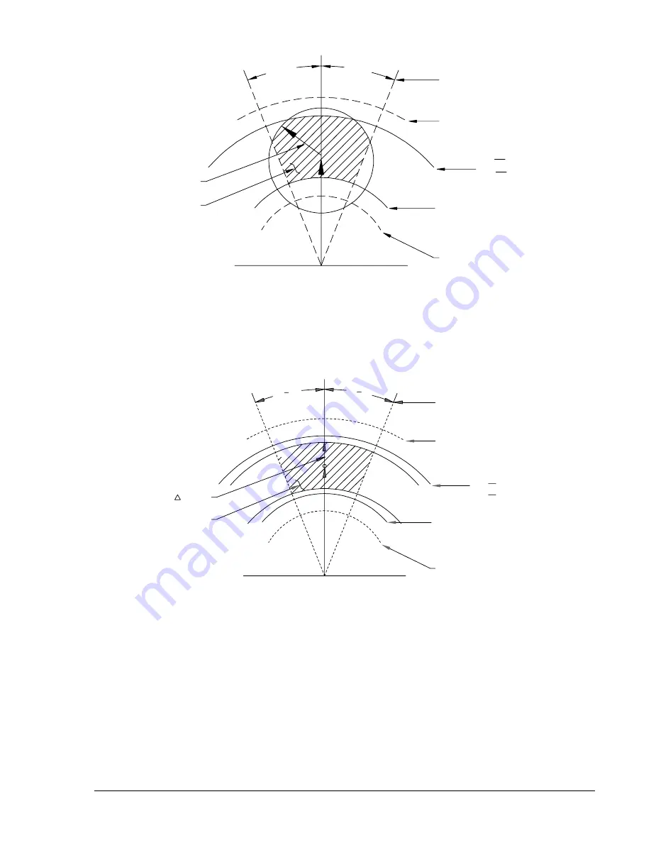
θ
V ADJ
∆
ALLOWABLE
CLOSING ZONE
PHASE ANGLE ADJ
135V (MAX)
DL /OV ADJ (LINE)
DB /OV ADJ (BUS)
LL ADJ (LINE)
LB ADJ (BUS)
60V (APPROX.) FIXED
MINIMUM VOLTAGE
P1004-35.vsd
01-29-01
θ
Figure 1-2. Closing Zone (Phasor Sensing)
P H A S E A N G L E A D J
1 3 5 V ( M A X )
D L / O V A D J ( L I N E )
DB/OV ADJ (BUS)
LL ADJ (LINE)
L B A D J ( B U S )
6 0 V ( A P P R O X . ) F I X E D
M I N I M U M V O L T A G E
0
0
V A D J
A L L O W A B L E
C L O S I N G Z O N E
P 1 0 0 4 - 3 8 . v s d
0 1 - 2 9 - 0 1
Figure 1-3. Closing Zone (Average Sensing)
Option 2-A, 2-B, or 2-C (Average Voltage Difference)
This option is similar to option 2-T, 2-R, or 2-U except for the sensing method. This option provides
average voltage sensing instead of phasor voltage sensing. This provides a constant
∆
V setting
independent of the phase relationship between the line and bus voltages.
Figure 1-5 may be used as an aid in formulating the voltage difference control settings. Note that the
center reference phasor (
V
B
) represents the monitored bus voltage, while the adjacent phasor (
V
L
)
represents the monitored line voltage. The voltage difference control (
∆
V) forms an area of acceptance
limit.
www
. ElectricalPartManuals
. com


