2-4
BE1-25 Human-Machine Interface
Callout
Control or Indicator
Function
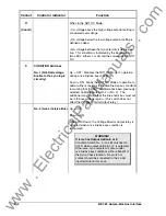
R
(Cont'd)
When in the NOT OV Mode:
(1) A voltage above the high voltage setpoint setting is
considered overvoltage.
(2) A voltage below the low voltage setpoint setting is
defined as dead.
(3) A voltage between the two setpoints is defined as
live. This condition is indicated by the illumination of
two LEDs: either LL or LB and the corresponding NOT
OV.
S
CONDITION Switches
No. 1 (Not-Overvoltage
Enable to the sync logic
circuitry)
Up = OFF: Disables the NOT OV Mode of operation
during a live line/live bus condition.
Down = ON: Allows the NOT OV Mode of operation to
add a further constraint to the live line/live bus condition
(assuming that the NOT OV Mode has been previously
selected on Mode Switch No. 1 or No. 2). The
additional constraint is that the line and/or bus must not
be in the overvoltage region. (This switch does not
affect the Voltage Monitor Output relay.)
No. 2 (Live Line/Live Bus)
Up = OFF
Down = ON
When ON (Down), the Voltage Monitor Output relay is
actuated when a live line/live bus condition is
recognized.
WARNING!
If relay has Output Option E or F:
Condition Switch No. 2 (LL-LB) must be Up
(OFF) when output option E or F is selected.
Otherwise, sync outputs will occur under
live line/live bus conditions without benefit of
the Sync-Check function. No switch or
contact should be connected to the LL-LB
input terminal in this case.
www
. ElectricalPartManuals
. com


