3-4
BE1-25 Functional Description
Another output from the voltage monitor selection logic serves as an additional qualifier for the timer in the
sync output circuit. The specific conditions being monitored depend upon whether NORMAL or NOT OV
operation is used. Live line and live bus is monitored if NORMAL Mode is selected. Live line, live bus,
and Not Overvoltage is monitored if NOT OV Mode is selected.
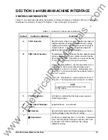
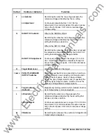
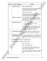
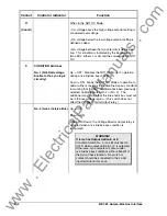
Detailed instructions and precautions for programming the Mode and Condition switches are provided in
Table 2-1, callouts R and S. The location of the switches is shown in Figure 2-2.
Target Indicator Option
Each target indicator is visible on the front panel of the relay with the cover in place. When tripped, the
disc in the target changes from black to red and is magnetically latched in this position. To reset the target
after an abnormal system condition has been cleared, manually raise the target reset lever on the front of
the relay (or its extension which protrudes through the bottom of the front cover).
When a Target option is specified as either A or B as described in the following paragraphs and shown in
Figure 1-6, a magnetically latched indicator is incorporated in the front panel. When a target is tripped, a
SYNC output occurs. The target may be actuated by either of two methods:
Type A
Type A target (referred to as internally operated) is actuated by an integral driver circuit that responds
directly to the relay internal logic. This type of target is tripped regardless of the amount of current flowing
through the output contact.
Type B
Type B target (referred to as current operated) is actuated when a minimum of 0.2 ampere flows through
the SYNC output contact. To accomplish this, a special reed relay is placed in series with the contact to
signal the target indicator. (The series impedance of the reed relay is less than 0.1 ohm.) Current in the
output circuit must be limited to 30 amperes for 0.2 seconds, 7 amperes for 2 minutes, and 3 amperes
continuously.
www
. ElectricalPartManuals
. com


