BE1-25 Installation
4-5
1 0
9
2
1
1.47
(37.3)
3.20
(81.3)
4.28
(108.7)
.50
(12.7)
TYP.
1.00
(25.4)
2.63
(66.8)
.69
(17.5)
.25
(6.4)
5.25
(133.4)
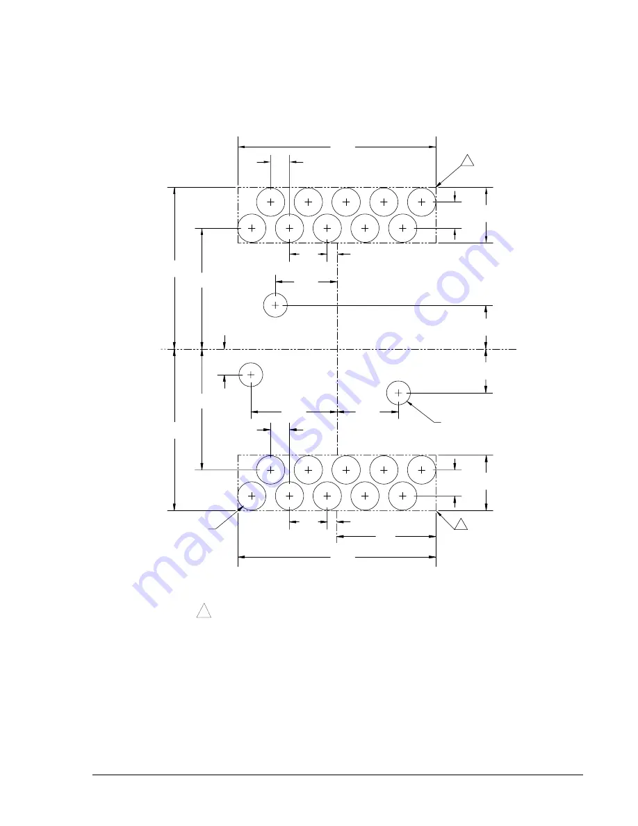
.75 (19.1) DIA.
20 PLACES
1
.63 (16.0) DIA.
3 PLACES
1
0 1 - 3 0 - 0 1
D 1 4 2 7 - 0 5
1.16
(29.5)
1.16
.68
(17.3)
1.63
(41.4)
2.28
(57.9)
(17.5)
.69
(37.3)
1.47
1 1
1 2
1 9
2 0
TYP.
(12.7)
.50
(108.7)
4.28
(81.3)
3.20
(133.4)
5.25
(6.4)
.25
(25.4)
1.00
1.63
(41.4)
(29.5)
Notes:
1
Optional rectangular cutout may replace the ten drilled
holes.
2.
Terminal numbers shown are as viewed from rear of
relay.
Figure 4-5. Panel Drilling Diagram (Projection Mounting)
www
. ElectricalPartManuals
. com

