5-4
BE1-25 Testing
PHASE CONTROL
BETWEEN THE SOURCES.
BE1-25
D1057-08
3-9-92
1
SPECIFIED
INPUT
POWER
1
NO
POLARITY
COM.
COM.
COM.
EXPAND
PHASE
ANGLE
OPTION
BUS
LINE
52b
TB2 TERM. STRIP
(AT REAR OF CASE)
USE OF TERMINAL
WILL VARY DEPENDING
ON OPTIONS.
SYNC
OUTPUT
2
5
TIMER
AUXILIARY SYNC OUTPUT
(MAY BE FORM A, B, OR C,
DEPENDING ON OPTIONS.)
LINE AND BUS VOLTAGE
MONITOR OUTPUT (OPTIONAL)
BE1-25 RELAY
CONTACT SENSING INPUTS
(SIMULATED BY
SWITCHES ILLUSTRATED)
FOR NON-ISOLATED SENSING:
INSERT DC POWER FROM TERMINALS
3 AND 4 OF RELAY.
FOR ISOLATED SENSING:
CONNECT A TO B.
EXTERNAL
CONDITION
SWITCHES
(SIMULATED)
3
4
6
7
8
9
15
14
3
2
1
4
19
1
10
11
18
19
20
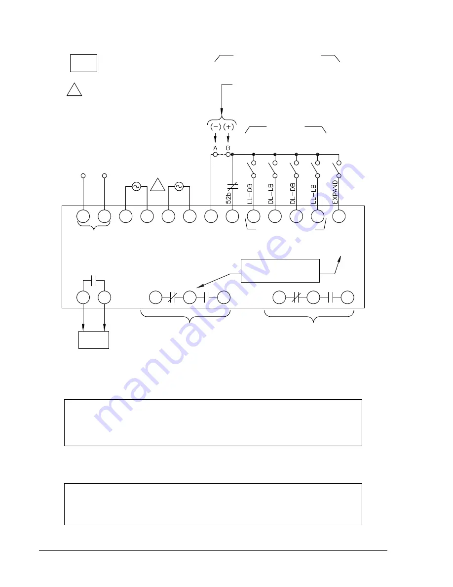
Figure 5-2. Test Setup (Typical)
Test Procedure
NOTE
A 00 setting of either control must inhibit the Sync-Check function.
If target option B (current operated target) is present, check that targets operate at
closure of the sync contacts. (Requires a minimum of 0.2 A in the output circuit.)
Step 1.
Confirm proper sync-check operation at selected PHASE ANGLE settings with TIME DELAY set
at minimum (for convenience). Check that go/no-go operation is within specs.
NOTE
When making this test, observe that the PHASE ANGLE LED is turned ON during the
delay period, and that the SYNC LED flashes when the output contacts close. (Both
LEDs go out as soon as the 52b input is open.)
If auxiliary contacts are supplied, check for proper switching action as relay cycles.
www
. ElectricalPartManuals
. com


