5-6
BE1-25 Testing
(b) If the relay is not equipped with a separate relay for Voltage Monitor (output options G and H),
set TIME DELAY to 99 seconds. This allows the convenience of using in-phase voltages for
testing non-synchronous functions (without unwanted SYNC contact closures).
(c) Apply simulated line and bus voltages, adjusted to check the bus and line voltage criteria
given in Table 5-1. To be valid, an output must occur immediately after line and bus voltages
are applied.
NOTE
In some units, both the internal Condition Switches and the external condition sensing
inputs are present and in parallel. Take care that only one input method is utilized when
testing the relay, and (most importantly) after the relay is installed.
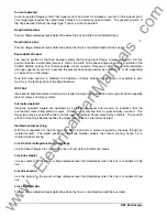
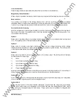
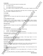
Table 5-1. NORMAL Mode Testing
No output* throughout voltage range.
Condition Switch
1
Up
2
Up
3
Up
4
Up
5
Up
Mode Switch
1
Up
2
Up
Output* only when bus input voltage is greater than 80 volts and line is less than 30 volts.
Condition Switch
1
Up
2
Up
3
Down
4
Up
5
Up
Mode Switch
1
Up
2
Up
Output* only when bus input voltage is less than 30 volts and line is greater than 80 volts.
Condition Switch
1
Up
2
Up
3
Up
4
Down
5
Up
Mode Switch
1
Up
2
Up
www
. ElectricalPartManuals
. com


