6-2
BE1-25 Maintenance
Test plugs consist of a black and red phenolic molding with twenty electrically separated contact fingers
connected to ten coaxial binding posts. The ten fingers on the black side are connected to the inner
binding posts (black thumb nuts) and tap into the relay internal circuitry. The ten fingers on the red side of
the test plug are connected to the outer binding posts (red thumb nuts) and also connect to the relay case
terminals.
When testing circuits connected to the bottom set of case terminals, the test plug is inserted with the
numbers 1 through 10 facing up. Similarly, when using the test plug in the upper part of the relay, the
numbers 11 through 20 are face up. It is impossible, due to the construction of the test plug, to insert it
with the wrong orientation.
TEST PLUG ADAPTER
General
BE1-25 relays equipped with external contacts to control the Condition Switches (option 2-C, 2-U, or 2-V)
have a voltage-dropping Resistor Module mounted externally on the back side of the case. (Refer to
Figures 4-7 and 4-9). Functionally, this module is part of the internal circuitry despite its external location.
When using the test plug on these relays, compensating resistors must be added. The most convenient
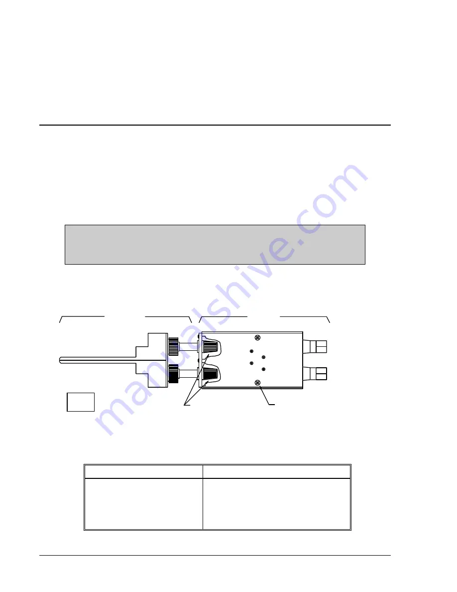
method is to use the Test Plug Adapter shown in Figure 6-1. This adapter is attached to the test plug
before inserting the test plug into the relay upper jack. See Table 6-1 for the correct adapter.
CAUTION
Do not attempt to use an adapter for an application not specified in Table 6-1.
The surface of 230 V adapter units may become hot.
If the correct Test Plug Adapter is not readily available, an alternative procedure is described at the end of
this section.
TEST PLUG
(BASLER P/N 10095 OR G.E. P/N 12XLA12A1)
(BASLER P/N 9 1701 11 XXX)
ADAPTER
(TYPICAL 10 PLACES)
BLACK THUMB NUTS
(TYPICAL 4 PLACES)
RETAINER SCREW
BE1-79M
D806-012
6-24-91
Figure 6-1. Adapter and Test Plug
Table 6-1. Test Plug Adapter Requirements
Nominal Power Supply Type
Test Plug Adapter Part Number
24V
None Required
48V
9 1701 11 101
125V
9 1701 11 103
230V
9 1701 11 105
www
. ElectricalPartManuals
. com


