background image

BE1-32R, BE1-32R O/U

11

ORDERING

MODEL NUMBER

BE1-32R Directional Power Relay and BE1-32 O/U

Directional Over/Underpower Relay.

STYLE NUMBER

The style number appears on the front panel, drawout

cradle, and inside the case assembly. This style

number is an alphanumeric combination of characters

identifying the features included in a particular unit. The

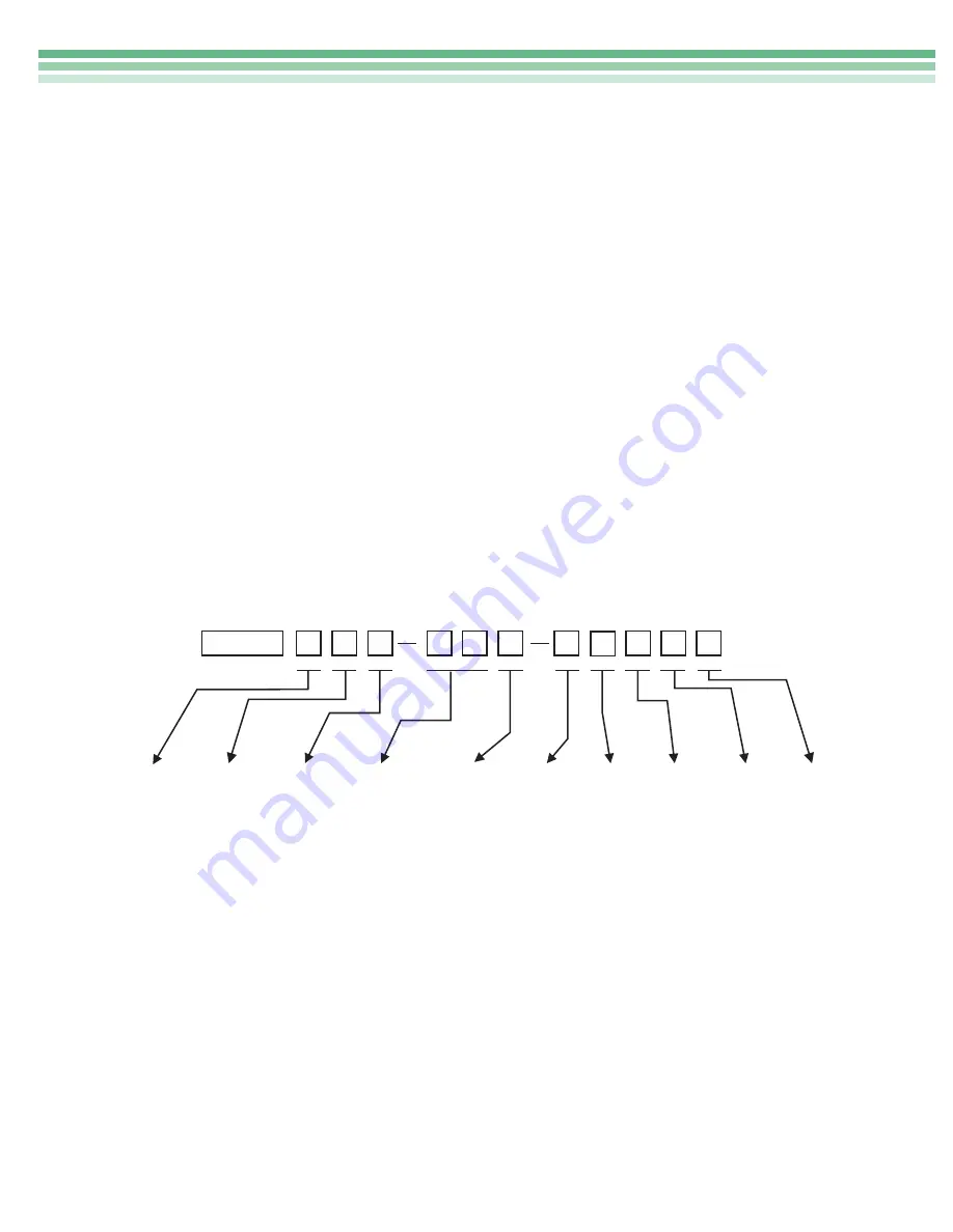
sample style number below illustrates the manner in

which the various features are designated. The Style

Number Identification Chart (page 12) defines each of

the options and characteristics available for this device.

SAMPLE STYLE NUMBER A1E-A1P-A0N2F

The style number above describes a BE1-32R Direc-

tional Power Relay having the following features.

Sensing Input Type (A) Single-phase current and

L-N voltage sensing

Sensing Input Range (1)120 Vac, 0.5-20W

HOW TO ORDER:

Designate the model number followed by the complete

Style Number.

Complete the Style Number by selecting one feature

from each column of the Style Number Identification

Chart and entering its designation letter or number into

the appropriate square. (Two squares are used to

indicate time delay characteristics.) All squares must

be completed.

Output

(E)

One Output relay with

normally open contacts

Timing

(A1)

Instantaneous timing

Power Supply (P)

125 Vdc/120 Vac input

power supply

Target

(A)

One internally operated target

Option 1

(0)

None

Option 2

(N)

None

Option 3

(2)

One auxiliary output relay

with normally closed contacts

Option 4

(F)

Semi-flush mounting

NOTE: The description of a complete relay must

include both the model number and the style number.

STANDARD ACCESSORIES:

The following accessories are available for the BE1-32R

or BE1-32 O/U Directional Power Relays.

Test Plug

To allow testing of the relay without removing system

wiring, order two test plugs, Basler Electric part num-

ber 10095.

Extender Board

The extender board permits troubleshooting of the

printed circuit boards outside of the relay cradle. Order

Basler Electric part number 9 1655 00 100.

SENSING
INPUT
TYPE

SENSING
INPUT
RANGE

OUTPUT

TIMING

POWER
SUPPLY

TARGET

OPTION

4

OPTION

3

OPTION

2

OPTION

1

BE1-32R

A

1

E

A

1

P

A

0

N

2

F

Summary of Contents for BE1-32

Page 1: ...rations are available including single phase and three phase 3 and 4 wire systems Sensing ranges available from 0 5 to 6000 watts secondary Instantaneous definite and inverse timing characteristics av...

Page 2: ...and continues to run as a synchronous motor drawing sufficient power from the system to drive the prime mover Sustained motoring can cause severe damage to the prime mover The Directional Power Relay...

Page 3: ...rovide adequate protection for the distribution system the overpower function is used to sense overload conditions on each transformer and the underpower function is used to sense power flowing throug...

Page 4: ...nts If sensing input range 1 4 or 7 is selected the input transformers are capable of 7 A continuous current 10 A for 1 minute and 140 A for 1 second However reactive power is defined by the equation...

Page 5: ...sing type and their calibration Type A Sensing Single Phase Figure 7 The type A sensing configuration monitors line to neutral voltage and a single phase current of a three phase four wire circuit and...

Page 6: ...en 0 9 and 0 5 The range of voltage for proper operation is 40 to 150 percent of the nominal value When the calculated value for power exceeds the over power pickup setting or falls below the underpow...

Page 7: ...nverse time delayed trip is available for the overpower function only The inverse time delay curve is adjust able from 01 to 99 by means of a front panel thumbwheel switch Incrementing the thumbwheel...

Page 8: ...alified to ANSI IEEE C37 90 1 1989 Fast Transient Test IMPULSE TEST Qualified to IEC 255 5 MECHANICAL Operating Temperature 40 C 40 F to 70 C 158 F Storage Temperature 65 C 85 F to 100 C 212 F Weight...

Page 9: ...BE1 32R BE1 32R O U 9 CONNECTIONS Figure 13 Sensing Connections Continued overpage 52 BE1 32 A B C N 5 6 8 9 TYPE A SENSING GENERATOR TRIPPING DIRECTION...

Page 10: ...10 BE1 32R BE1 32R O U CONNECTIONS continued Figure 14 Control Circuits Figure 13 continued Sensing Connections...

Page 11: ...he Style Number Identification Chart and entering its designation letter or number into the appropriate square Two squares are used to indicate time delay characteristics All squares must be completed...

Page 12: ...BER IDENTIFICATION CHART ROUTE 143 BOX 269 HIGHLAND ILLINOIS U S A 62249 PHONE 618 654 2341 FAX 618 654 2351 P A E Les Pins 67319 Wasselonne Cedex FRANCE PHONE 33 3 88 87 1010 FAX 33 3 88 87 0808 http...

Reviews: