BE1-32R, BE1-32R O/U
3
APPLICATION
(continued)
When the generator is paralleled and loaded, the kW
signal will decrease by the amount of load the generator
accepted. An underpower relay can measure utility
power and generate a “stop” signal when utility power
decreased below a selected level. A definite time delay
will generally be provided for the “stop” signal of one
minute or more. The Basler Model BE1-32 O/U Power
Relay incorporates both over and under power sensing
in one relay, which makes it ideal for this application.
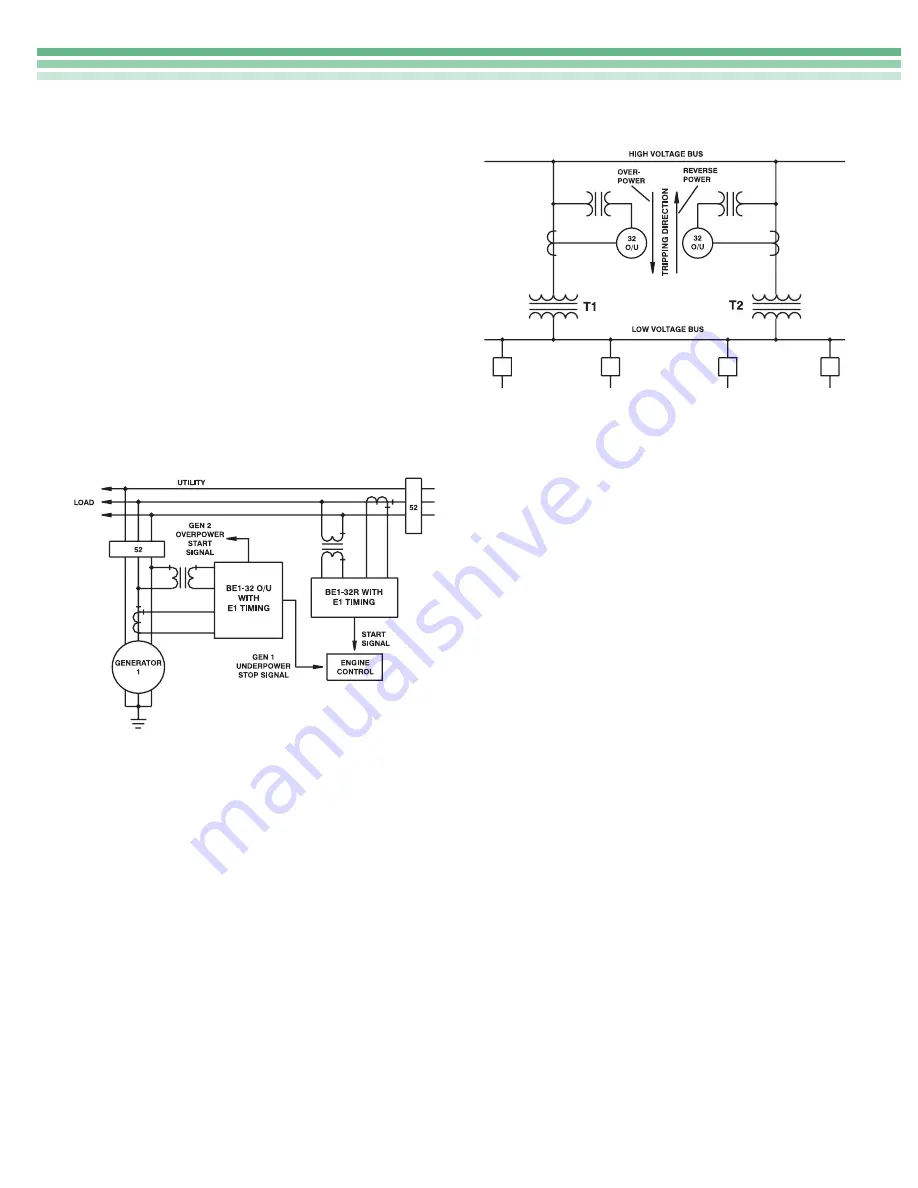
In the second configuration (Figure 3) the “start” signal
is generated as in that of Figure 2. The setpoint of the
start signal should be above the import power setting.
The “stop” signal will require an underpower relay on
the generator output. This system is illustrated in Figure
3.
EXAMPLE 3 - GENERATOR OVERLOAD
Refer to Figure 3. Whenever excessive load has been
connected to a generating system, the Power Relay will
initiate the corrective action by energizing an alarm to
alert the station operator or will initiate an automatic
sequence to either shed non-critical load or start and
parallel an in-house generator to assume the excess
load.
EXAMPLE 4 - DISTRIBUTION SYSTEM OVERLOAD
Another typical use, addressing excessive load, con-
cerns distribution protection, see Figure 4. A high-
voltage bus supplies two transformers. T1 and T2
together can supply all connected load. However,
neither T1 or T2 is capable of supplying the total load.
To provide adequate protection for the distribution
system, the overpower function is used to sense
overload conditions on each transformer and the
underpower function is used to sense power flowing
through the transformers in an undesired direction.
Figure 3 - Power Relay Start/Stop Control
EXAMPLE 5 - REACTIVE POWER (VARs)
DETECTION
This example deals with the Directional Power Relay’s
ability to measure real or reactive power.
Real power (watts) is supplied to the generator by the
prime mover, and reactive power (vars) is supplied to
the field by the exciter. When field excitation is signifi-
cantly reduced and the connected system can provide
sufficient reactive power to maintain the generator’s
terminal voltage, reactive power will flow into the
machine and cause it to operate as an induction
generator with essentially the same kW output. This
situation causes problems; first, the additional reactive
loading of the faulty generator must be redistributed to
other synchronous generators on the system. Sec-
ondly, a synchronous generator is not designed to
function as an induction generator. Excessive heating
occurs in the damper (Amortisseur) windings, slot
wedges, and in the surface iron of the rotor due to slip
frequency current flow which results when a synchro-
nous generator is operated as an induction generator.
The Directional Power Relay can be applied to respond
to this reactive power flow.
The Basler BE1-32 Directional Power Relay is designed
to respond to true power as defined by the equation:
P = El cos
Θ
where: P = real power (watts)
E = effective emf or system voltage
I = effective current
Θ
= the phase angle between E and I
Figure 4 - Distribution Protection


