6
BE1-32R, BE1-32R O/U
SPECIFICATIONS
(continued)
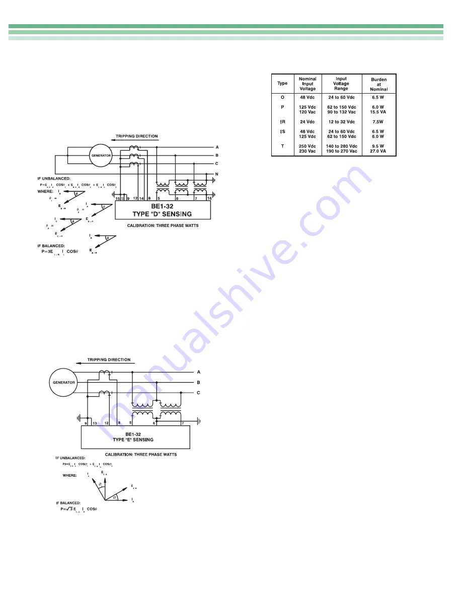
Type D Sensing: Three-Phase (Figure 10). The type D
sensing configuration monitors three line-to-neutral
voltages and three phase currents of a three-phase, four-
wire circuit and calculates the power flowing in the
tripping direction. Relays with this sensing type are
calibrated in three-phase watts.
Type E Sensing: Three-Phase (Figure 11). The type E
sensing configuration monitors three line-to-line voltages
and two of the phase currents of a three-phase, three-
wire circuit and calculates the power flowing in the
tripping direction. The power equation assumes that
conditions are balanced. Relays with this sensing type
are calibrated in three-phase watts. Note: Type E
configurations are phase rotation sensitive.
Power Supply
One of five power supply boxes may be selected to
provide internal operating power. They are described in
Table 1.
POWER RANGE PICKUP
Overpower pickup of the relay is adjustable by means of
a front panel 10 position rotary TAP select switch used in
conjunction with the front panel HIGH/LOW switch over
the defined ranges listed in Table 2. Underpower pickup
is continuously adjustable from 10 to 95% of the selected
overpower tap. Pickup accuracy is within 2% (or 0.05
watts) of the front panel setting for unity power factor.
Pickup accuracy is within 5% of the front panel setting for
all other power factors between 0.9 and 0.5. The range of
voltage for proper operation is 40 to 150 percent of the
nominal value.
When the calculated value for power exceeds the over-
power pickup setting or falls below the underpower
pickup setting and is in the tripping direction, the appro-
priate LED is illuminated and timing is initiated. One
indicating LED is provided for each measuring function
within the relay.
KW TRANSDUCER
The kW Transducer samples the current and voltage of
each phase on a continuous basis. The resulting signals
representing current and voltage are multiplied and
integrated to develop a dc voltage level that is representa-
tive of true kW.
COMPARATOR CIRCUITS
The dc output of the kW Transducer is then compared to
front panel settings for underpower and/or overpower.
When the reference level of the comparator (or compara-
tors if applicable) is crossed, the output of the compara-
tor is used to either energize the appropriate output (if
instantaneous timing has been specified) or to initiate the
timing circuits (definite, or inverse).
TIMING
Time delay is defined as the elapsed time between the
application of the condition to the input terminals of the
relay and the transition of the output contacts.
† Type R Power Supply may require 14 Vdc to begin operation. Once operating, the
voltage may be reduced to 12 Vdc.
‡ Type S Power Supply is field selectable for 48 or 125 Vdc. Selection must be
implemented at time of installation. This Power Supply option is factory set for 125 Vdc.
Table 1 - Power Supply Options
Figure 10 - Three Phase, Type D Sensing
Figure 11 - Three Phase, Type E Sensing


