BE1-40Q Human-Machine Interface
2-1
SECTION 2 • HUMAN-MACHINE INTERFACE
CONTROLS AND INDICATORS
Table 2-1 lists and briefly describes the operator controls and indicators of the BE1-40Q Overexcitation
Relay. Reference the call-out letters to Figure 2-1.
Table 2-1. Controls and Indicators
Letter
Control or Indicator
Function or Indicator
A
TAP
Switch
A ten-position rotary switch sets the pickup point
when used in conjunction with the
RANGE
Switch
(see I). Pickup levels (in vars) are labeled on the
Tap Range Chart (see G).
B
PICKUP
Indicator
LED illuminates to indicate that the pickup level
has been exceeded.
C
POWER
Indicator
LED illuminates to indicate that the relay power
supply is functioning properly.
D
Target Reset Lever
Linkage extends through bottom of front cover to
reset the target indicator.
E
Target Indicator (Optional)
Magnetically latching indicator is tripped to red to
indicate that the output relay either has been
energized (internally operated) or that a minimum
of 0.2 amperes has flowed through the contacts
(current operated).
F
PUSH-TO-ENERGIZE
(Optional)
Momentary pushbutton is accessible through the
front panel and used to test the output relay and
verify system wiring.
G
Tap Range Chart
Provides an index of reactive power levels (in
vars) that correspond to the
TAP
Switch positions.
H
TIME DELAY
Selectors
Two thumbwheel switches select the trip time
delay. The left thumbwheel represents seconds;
the right thumbwheel represents tenths of a
second. A
TIME DELAY
setting of 00 indicates
instantaneous trip time.
I
RANGE
Switch
Two-position switch selects the reactive power
range (
HI
or
LOW
) desired.
Summary of Contents for BE1-40Q
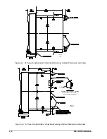
Page 13: ...2 2 BE1 40Q Human Machine Interface Figure 2 1 Location of Controls and Indicators ...
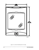
Page 19: ...4 2 BE1 40Q Installation 2 02 01 D1427 01 Figure 4 1 S1 Case Outline Dimensions Front View ...
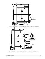
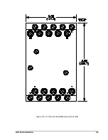
Page 22: ...BE1 40Q Installation 4 5 Figure 4 6 S1 Case Outline Dimensions Rear View ...
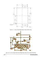
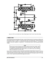
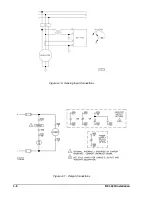
Page 25: ...4 8 BE1 40Q Installation Figure 4 10 Sensing Input Connections Figure 4 11 Output Connections ...
Page 35: ...5 8 BE1 40Q Setting and Testing Figure 5 4 Blank Graph ...


