Summary of Contents for BE1-40Q
Page 13: ...2 2 BE1 40Q Human Machine Interface Figure 2 1 Location of Controls and Indicators ...
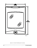
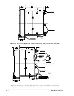
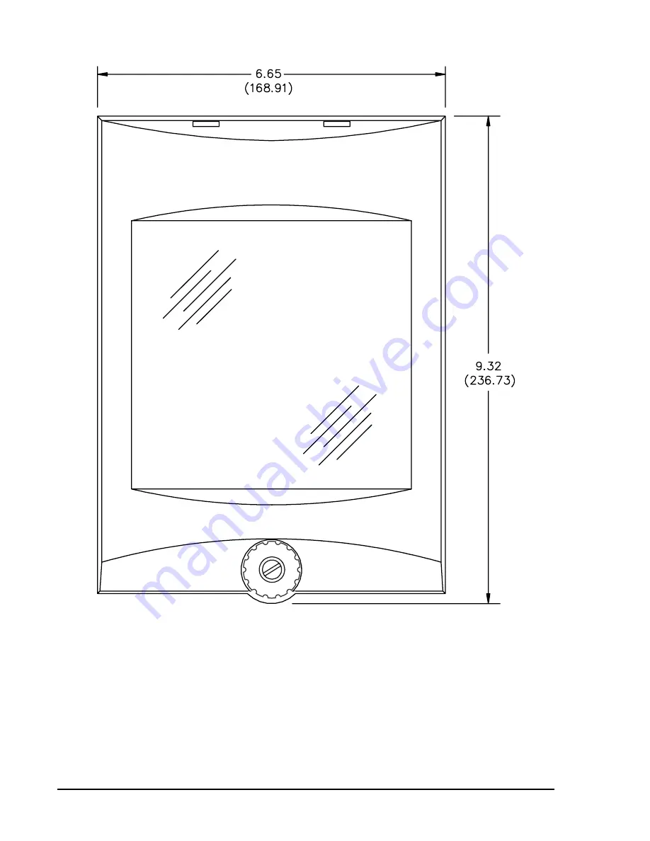
Page 19: ...4 2 BE1 40Q Installation 2 02 01 D1427 01 Figure 4 1 S1 Case Outline Dimensions Front View ...
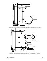
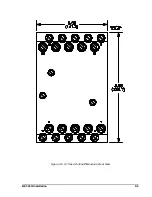
Page 22: ...BE1 40Q Installation 4 5 Figure 4 6 S1 Case Outline Dimensions Rear View ...
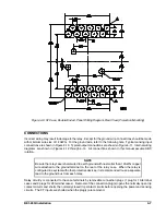
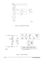
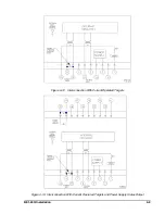
Page 25: ...4 8 BE1 40Q Installation Figure 4 10 Sensing Input Connections Figure 4 11 Output Connections ...
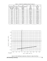
Page 35: ...5 8 BE1 40Q Setting and Testing Figure 5 4 Blank Graph ...


