BE1-40Q Setting and Testing
5-1
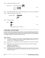
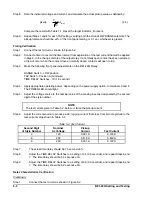
Three
!
phase primary vars
"
0.4
×
rated power
"
0.4
×
100 MVA
"
40 Mvar
Single
!
phase primary vars
"
13.33 Mvar
(4.1)
SECTION 5 • SETTING AND TESTING
SETTING
Setting the pickup value of BE1-40Q Relays is facilitated by using the capability curves supplied by the
generator manufacturer as shown previously in the examples in Section 1. The figure for relay operating
characteristics is repeated here as Figure 5-1. Note that the line representing the relay characteristic is
positioned on the curve 8
!
from horizontal and just above the point where the steady state stability limit arc
intersects the capability curve. (The 8
!
slope applies to all BE1-40Q Relays.)
Figure 5-1. An Example of BE1-40Q Relay Operating Characteristics
The pickup setting is determined by the point where the BE1-40Q characteristic intersects the Q axis in per
unit (pu) quantities. Therefore, for the example shown in Figure 5-1, the pickup is -0.4 pu. The actual per
unit pickup setting for your relay is determined by your specific application.
Per Unit Conversion Example
The per unit quantity is converted to a TAP Switch setting by the procedure described in the following
example.
Given:
Rated power = 100 MVA
Rated voltage = 12.8 kV
CT ratio = 5000/5
PT ratio = 12800/120
Step 1.
Determine the desired primary vars.
Summary of Contents for BE1-40Q
Page 13: ...2 2 BE1 40Q Human Machine Interface Figure 2 1 Location of Controls and Indicators ...
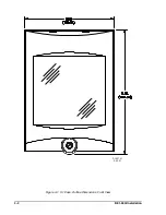
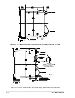
Page 19: ...4 2 BE1 40Q Installation 2 02 01 D1427 01 Figure 4 1 S1 Case Outline Dimensions Front View ...
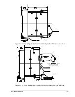
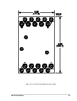
Page 22: ...BE1 40Q Installation 4 5 Figure 4 6 S1 Case Outline Dimensions Rear View ...
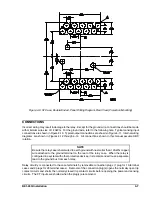
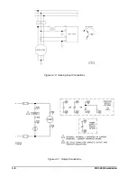
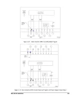
Page 25: ...4 8 BE1 40Q Installation Figure 4 10 Sensing Input Connections Figure 4 11 Output Connections ...
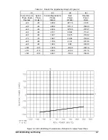
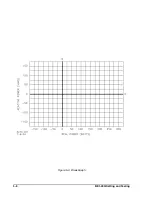
Page 35: ...5 8 BE1 40Q Setting and Testing Figure 5 4 Blank Graph ...


