5-6
BE1-40Q Setting and Testing
NOTE
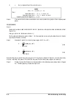
If V =
"
V
"
#
"
and I =
"
I
"
#
#
,
Then:
Real power (P) =
"
V
"
x
"
I
"
cos(
"
-
#
),
Reactive power (Q) =
"
V
"
x
"
I
"
sin(
"
-
#
), and
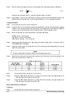
System power factor angle (
!
) =
"
-
#
P
"
120
3
(3.806)cos(
!
20
!
)
"
247.8 W
(4.8)
Q
"
120
3
(3.806)sin(
!
20
!
)
"
!
90.18vars
(4.9)
!
=
the (-) angle setting of the current source.
Step 3.
The results from the above calculations can now be plotted on a graph of the complex power
plane.
Graph Example
Given:
Relay style number is BE1-40Q F3E E1P B1S1F. (Reference the Style Number Identification Chart,
Figure 1-4.)
Pickup is set to 125. (Reference Table 1-1.)
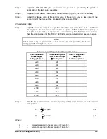
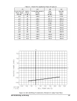
Test results are obtained as given in Step 1. For this example, we are using the data shown in columns
[1] and [2] of Table 5-4, below.
Step 1.
Calculate P and Q for a current phase angle of 20
!
(
!
= -20
!
).
Note that the above results for a phase angle of -20
!
have been entered in Table 5-4, columns [3] and [4],
first row. Similarly, the values of P and Q can be solved for the other phase angles of column [1].
Step 2.
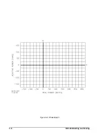
Finally, the data from Table 5-4 is shown plotted on the complex power plane shown in Figure
5-3. A blank graph is provided as Figure 5-4.
Summary of Contents for BE1-40Q
Page 13: ...2 2 BE1 40Q Human Machine Interface Figure 2 1 Location of Controls and Indicators ...
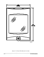
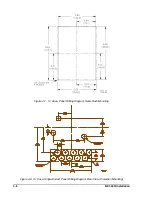
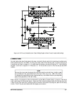
Page 19: ...4 2 BE1 40Q Installation 2 02 01 D1427 01 Figure 4 1 S1 Case Outline Dimensions Front View ...
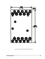
Page 22: ...BE1 40Q Installation 4 5 Figure 4 6 S1 Case Outline Dimensions Rear View ...
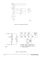
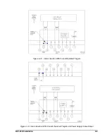
Page 25: ...4 8 BE1 40Q Installation Figure 4 10 Sensing Input Connections Figure 4 11 Output Connections ...
Page 35: ...5 8 BE1 40Q Setting and Testing Figure 5 4 Blank Graph ...

