1-4
BE1-40Q General Information
SPECIFICATIONS
Current Sensing
Unit is designed to operate from the secondary of a standard current
transformer rated at 5 A, 50 and 60 Hz (based on configuration). Internal
current sensing transformers are rated at 10 A continuous, 15 A for 1
minute, and 200 A for 1 second.
Current Sensing Burden
Maximum sensing burden is less than 0.1 ohm at pickup over the
frequency range of 45 to 65 Hz.
Voltage Sensing
Three line-to-line voltage sensing inputs are available: 120, 208, and 240
Vac (nominal). Each have a burden that is less than 1 VA over the
frequency range of 45 to 65 Hz.
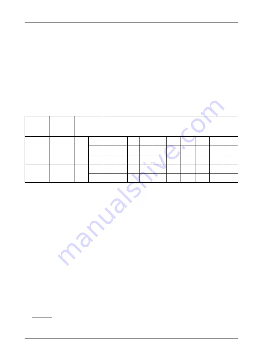
Pickup Range
Refer to Table 1-1.
Table 1-1. Pickup Setting
SENSING
INPUT
TYPE
NOMINAL
VOLTS
SENSING
INPUT
RANGE
PICKUP SETTING (in secondary vars)
F & W
120
3
TAP
A
B
C
D
E
F
G
H
J
K
HI
100 200 300 400
500
600
700
800
900 1000
LOW
25
50
75
100
125
150
175
200
225
250
F & W
208 & 240 6 & 9
HI
200 400 600 800 1000 1200 1400 1600 1800 2000
LOW
50
100 150 200
250
300
350
400
450
500
Pickup Accuracy
±2% of the front panel setting or ±0.1 var, whichever is greater for a power
factor angle of -90
!
.
Dropout
Not less than 95% of actual pickup.
Time Delay Range
Definite time delay is adjustable by two front panel thumbwheels over a
range of 01 to 99 (0.1 to 9.9 seconds) in increments of 0.1 seconds. A
setting of 00 enables instantaneous operation.
Timing Accuracy
Shown in Figure 1-5. Note that each curve is slightly offset by a factor that
represents integration time. Repeatability is within ±5% or 25 milliseconds,
whichever is greater.
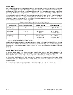
Power Supply
Power for the internal circuitry may be derived from a variety of ac or dc
power sources, as shown in Table 1-2.
Output Circuits
Output contacts are rated as follows:
Resistive:
120/240 Vac
Make 30 A for 0.2 seconds, carry 7 A continuously, and break 7 A.
250 Vdc
Make 30 A for 0.2 seconds, carry 7 A continuously, and break 0.3 A.
Inductive:
120/240 Vac,
Make 30 A for 0.2 seconds, carry 7 A continuously, and break 0.3 A.
125/250 Vdc
(L/R = 0.04).
Summary of Contents for BE1-40Q
Page 13: ...2 2 BE1 40Q Human Machine Interface Figure 2 1 Location of Controls and Indicators ...
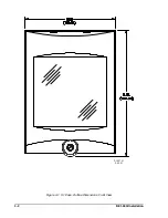
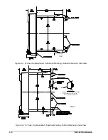
Page 19: ...4 2 BE1 40Q Installation 2 02 01 D1427 01 Figure 4 1 S1 Case Outline Dimensions Front View ...
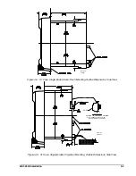
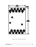
Page 22: ...BE1 40Q Installation 4 5 Figure 4 6 S1 Case Outline Dimensions Rear View ...
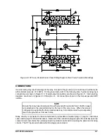
Page 25: ...4 8 BE1 40Q Installation Figure 4 10 Sensing Input Connections Figure 4 11 Output Connections ...
Page 35: ...5 8 BE1 40Q Setting and Testing Figure 5 4 Blank Graph ...


