3-2
BE1-47N Functional Description
comparison and timing functions.
LOW-PASS FILTER
The sensing circuits for over/undervoltage and negative sequence voltage are designed to operate on the
fundamental frequencies of 50 or 60 hertz. The low-pass filter is provided to pass the fundamental
frequencies and attenuate the higher ones.
NEGATIVE SEQUENCE VOLTAGE COMPARATOR
The proportionate negative sequence (V
2
) signal is compared to a reference level. When the level of the per
unit V
2
exceeds the reference level, the pickup indicator is illuminated and timing initiated.
OVER/UNDERVOLTAGE COMPARATOR
Optional single-phase over and undervoltage circuits operate on the voltage magnitude. The single-phase
ac signal is low-pass filtered and passed to the respective comparator where it is compared to the PICKUP
settings for each circuit. If either PICKUP setting has been exceeded (over or undervoltage) the appropriate
LED is turned ON and timing initiated.
TIMING
Three timing characteristics are optionally available; inverse time, definite time and instantaneous time (no
intentional delay). Timing for all three functions (47N - negative sequence voltage, 27 - undervoltage, 59 -
overvoltage) is completely independent and may be selected independently for each function. Definite Time
is adjustable from 0.1 to 9.9 seconds in increments of 0.1 seconds. Inverse Time is adjustable from 01 to
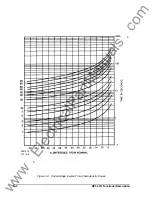
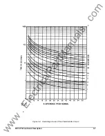
99 in increments of 1 (see Figures 3-2 through 3-4 Inverse Time Characteristic Curves). Instantaneous Time
is designated by a Time Delay setting of 00. Instantaneous response time is less than 50 milliseconds.
When evaluating inverse curves for the overvoltage or undervoltage function of the relay, it should be noted
that timing is based on the percent difference from system nominal. For example, refer to Figure 3-4. If the
monitored voltage was at a level that was 18% below system nominal, the portion of the curves below 18%
(i.e. 13%, 8%, etc.) has no effect on the units timing characteristics. In other words, the timing curve
beginning is dependent upon the monitored voltage percent difference from the system nominal voltage.
Inverse timing characteristics preceding this defined point are non-existent.
OUTPUTS
Output relays are provided for the trip functions (Negative Sequence Voltage and Under/Overvoltage).
Output relay contacts may be configured for normally open (NO) or normally closed (NC) operation. Auxiliary
output relays that operate at the same time as the trip output relays are also available. (See Option 3 of the
Style Chart).
INDICATORS
LEDs are provided to indicate the power supply is operating and that a particular function (i.e. 47N, 27, or
59) has exceeded its pickup point and the unit is timing. One indicator is provided for each measuring
function included within the relay.
TARGETS
Magnetically latched, manually reset target indicators are optionally available for the functions and may be
either internally operated (signal operated) or current operated (operated by a minimum of 0.2 Adc through
the output trip circuit).
www
. ElectricalPartManuals
. com


